Appendix C Keyboard
Compaq Personal Computers
Changed - April 1998
C-2
Keyboard
Interface
(System Unit)
Data/
CLK
C.2 KEYSTROKE PROCESSING
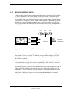
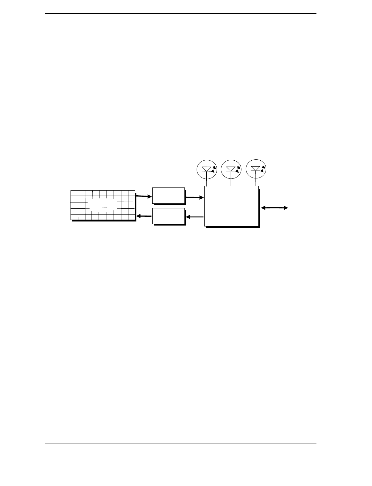
A functional block diagram of the keystroke processing elements is shown in Figure C-1. Power
(+5 VDC) is obtained from the system through the PS/2-type interface. The keyboard uses a
Z86C14 (or equivalent) microprocessor. The Z86C14 scans the key matrix drivers every 10 ms
for pressed keys while at the same time monitoring communications with the keyboard interface
of the system unit. When a key is pressed, a Make code is generated. A Break code is generated
when the key is released. The Make and Break codes are collectively referred to as scan codes.
All keys generate Make and Break codes with the exception of the Pause key, which generates a
Make code only.
Figure C–1.
Keystroke Processing Elements, Block Diagram
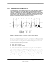
When the system is turned on, the keyboard processor generates a Power-On Reset (POR) signal
after a period of 150 ms to 2 seconds. The keyboard undergoes a Basic Assurance Test (BAT)
that checks for shorted keys and basic operation of the keyboard processor. The BAT takes from
300 to 500 ms to complete.
If the keyboard fails the BAT, an error code is sent to the CPU and the keyboard is disabled until
an input command is received. After successful completion of the POR and BAT, a completion
code (AAh) is sent to the CPU and the scanning process begins.
The keyboard processor includes a 16-byte FIFO buffer for holding scan codes until the system is
ready to receive them. Response and typematic codes are not buffered. If the buffer is full (16
bytes held) a 17
th
byte of a successive scan code results in an overrun condition and the overrun
code replaces the scan code byte and any additional scan code data (and the respective key
strokes) are lost. Multi-byte sequences must fit entirely into the buffer before the respective
keystroke can be registered.
Num
Lock
Caps
Lock
Scroll
Lock
Keyboard
Processor
Matrix
Drivers
Matrix
Receivers
Keyswitch
Matrix


