


Technical Reference Guide
Compaq Deskpro EN Series of Personal Computers
Desktop and Minitower Form Factors
Third Edition - September 1998
2-9
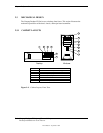
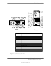
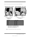
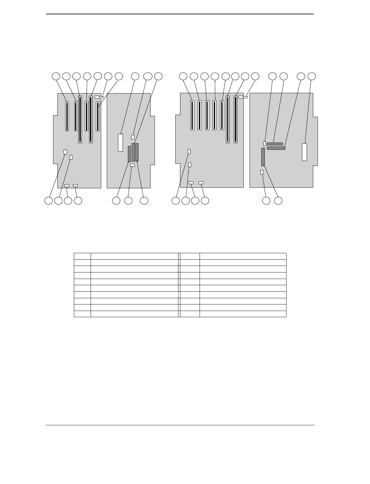
Figure 2-7 shows the connector and switch locations for the two types of backplane boards.
Item Function Item Function
1 PCI connector J20 (slot 1) 10 CD audio input header P7
2 PCI connector J21 (slot 2) 11 Secondary EIDE connector P21
3 ISA connector J10 [1] 12 Diskette drive connector P10
4 PCI connector J22 (slot 3) [2] 13 Primary EIDE connector P20
5 ISA connector J11 [3] 14 Power button/LED header P5
6 Smart Cover sensor switch 15 Fan header P8
7 PCI connector J23 (slot 4) [4] 16 Speaker header P6
8 PCI connector J24 (slot 5) 17 SCSI LED header P29
9 Power supply connector P1 18 NIC WOL header P9
NOTES:
[1] Shares slot with item 4 on desktop backplane (combo slot 1)
[2] Shares slot with item 3 on desktop backplane (combo slot 1)
[3] Shares slot with item 7 on desktop backplane (combo slot 2)
[4] Shares slot with item 5 on desktop backplane (combo slot 2)
[5] Later production units use the 009663-001 board
Figure 2–7. Backplane Board Connector, Header, and Switch Locations
1 3
4
5
2 8
1312
11
9
15
10
16
1210
6 7
14
11
Desktop Backplane Board
(P/N 008001-xxx
or 009663-xxx [5])
System Board Side Power Supply Side
17
Power Supply SideSystem Board Side
Minitower Backplane Board
(P/N 008058-xxx)
1 2
4
7 3 5 9
18 131415161718
6