


Technical Reference Guide
Compaq Deskpro EN Series of Personal Computers
Desktop and Minitower Form Factors
Third Edition–- September1998
6-9
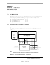
6.3.2 CONTROL
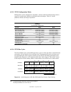
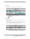
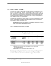
The audio subsystem is controlled through I/O mapped registers listed in Table 6-2.
Table 6–2.
Audio Subsystem I/O Map
Table 6-2.
Audio Subsystem I/O Map
I/O
Address Function
I/O
Address Function
201h Joystick 2nAh Read Buffer Input Data
2n0-2n3 FM Synthesizer Address/Data [1] 2nCh (Read) Status
2n4h Mixer Address 2nCh (Write) Command/Data
2n5h Mixer Data 2nEh Data Available Status
2n6h (Read) Activity/Power Status 2nFh FIFO I/O Address (Extended Mode)
2n6h (Write) Reset Control 3n0, 3n1h MPU-401 Port
2n7h Power Management 388-38Bh FM Synthesizer (alias of 2n0-2n3h)
2n8, 2n9h FM Synthesizer Address/Data [2] -- --
NOTES:
n = 2 for primary address (default), = 4 for secondary address.
[1] 20-voice operation
[2] 11-voice operation
Not supported
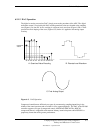
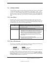
6.3.2.1 PCM Control
The audio subsystem can operate in either Sound Blaster-compatible mode (the default) or in
extended capability mode.
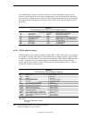
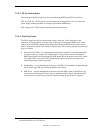
Table 6-3 lists the audio mixer control registers used by software written for Sound Blaster and
other common audio peripherals. These registers are accessed by writing the index value to I/O
port 2n4h and reading the value from or writing the value to I/O port 2n5h.
Table 6–3.
Compatibility Mode Audio Mixer Control Register Mapping
Table 6-3.
Compatibility Mode Audio Mixer Control Register Mapping
Index Function Index Function
00h Mixer Reset 22h Master Volume
04h Voice Volume 26h FM Volume
0Ah Mic Volume 28h CD Volume
0Ch ADC Recording Source [1] 2Eh Line Volume
0Eh Stereo/Mono Switch [1] -- --
NOTE: Refer to OEM’s ES1869 data sheet for detailed register descriptions.
[1] The filter functions used in Sound Blaster subsystems are not used in the audio subsystem.