


Chapter 4 System Support
Compaq Deskpro EN Series of Personal Computers
Desktop and Minitower Form Factors
Third Edition - September 1998
4-6
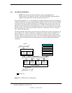
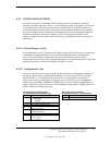
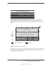
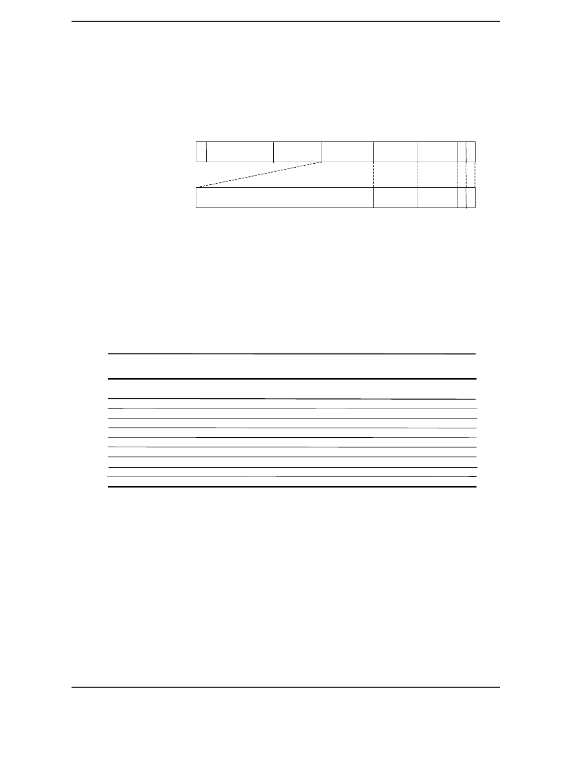
Figure 4-3 shows how the loading of 0CF8h results in a Type 0 configuration cycle on the PCI
bus. The Device Number (bits <15..11> determines which one of the AD31..11 lines is to be
asserted high for the IDSEL signal, which acts as a “chip select” function for the PCI device to be
configured.
Figure 4–3. Type 0 Configuration Cycle
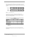
Type 0 configuration cycles are used for configuring devices on PCI bus # 0. Type 1
configuration cycles (reg. 0CF8h bits <1,0> = 01b) are passed on to PCI bus # 1 (if present).
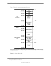
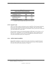
Table 4-3 shows the standard configuration of device numbers and IDSEL connections for
components and slots residing on a PCI bus.
Table 4–3. PCI Device Configuration Access
Table 4-3.
PCI Component Configuration Access
PCI Component Bus
Device
No. [1]
IDSEL
Wired to:
82443 (North Bridge) 0 0 AD11
AGP slot 1 0 AD16
USB 0 9 AD20
PCI Connector 1 (PCI slot 1) 0 13 AD24
PCI Connector 2 (PCI slot 2) 0 14 AD25
PCI Connector 3 (PCI slot 3) 0 15 AD26
PCI Connector 4 (PCI slot 4) 0 16 AD27
PCI Connector 5 (PCI slot 5) [2] 0 17 AD29
82371 (South Bridge) 0 20 AD31
NOTES
[1] CF8h bits <15..11>
[2] Minitower only.
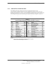
The function number (CF8h, bits <10..8>) is used to select a particular function within a
multifunction device. Configurable functions present in system as shipped from the factory are
listed in Table 4-4.
AD31..0
w/Type 0
Config. Cycle
Reserved
Device
Number
Function
Number
Register
Index
Bus
Number
3130 24 23
16 15 11 10 8 721 0
0 0
IDSEL (only one signal line asserted)
Function
Number
Register
Index
31
11 10 8
721 0
Register 0CF8h
Results in: