Chapter 5 Input/Output Interfaces
5-22 Compaq Deskpro EN Series of Personal Computers
Desktop and Minitower Form Factors
Third Edition – September 1998
5.5.4 PARALLEL INTERFACE PROGRAMMING
5.5.4.1 Parallel Interface Configuration
The parallel interface must be configured for a specific address range (LPT1, LPT2, etc.) and
also must be enabled before it can be used. When configured for EPP or ECP mode, additional
considerations must be taken into account. Address selection, enabling, and EPP/ECP mode
parameters of the parallel interface are affected through the PnP configuration registers of the
87307 I/O controller. Address selection and enabling are automatically done by the BIOS during
POST but can also be accomplished with the Setup utility and other software.
The PnP configuration registers are accessed through I/O registers 15Ch (index) and 15Dh
(data). The parallel interface is initiated by firmware selecting logical device 4 of the 87307. This
is accomplished by the following sequence:
1. Write 07h to I/O register 15Ch.
2. Write 04h to I/O register 15Dh (for selecting the parallel interface).
3. Write 30h to I/O register 15Ch.
4. Write 01h to I/O register 15Dh (this activates the interface).
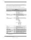
The parallel interface configuration registers are listed in the following table:
Table 5–12
. Parallel Interface Configuration Registers
Table 5-12.
Parallel Interface Configuration Registers
Index
Address Function R/W
Reset
Value
30h Activate R/W 01h
31h I/O Range Check R/W 00h
60h Base Address MSB R/W 02h
61h Base Address LSB R/W 78h
70h Interrupt Select R/W 07h
71h Interrupt Type R/W 00h
74h DMA Channel Select R/W 04h
75h Report DMA Assignment RO 04h
F0h Configuration Data R/W --


