Technical Reference Guide
Compaq Deskpro EN Series of Personal Computers
Desktop and Minitower Form Factors
Third Edition - September 1998
5-17
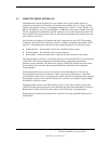
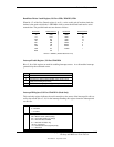
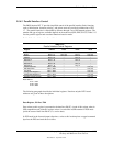
Baud Rate Divisor Latch Register, I/O Port 3F8h, 3F9h/2F8, 2F9h
When bit <7> of the Line Control register is set (1), a write to this pair of locations loads the
decimal value used to divide the 1.8462-MHz clock to create the desired baud rate for serial
transmission. The possible baud rates are shown as follows:
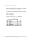
Baud Rate Decimal Divisor Baud Rate Decimal Divisor
50 2304 2400 48
75 1536 3600 32
110 1047 4800 24
134.5 857 7200 16
150 768 9600 12
300 384 19200 6
600 192 38400 3
1200 96 57600 2
1800 64 115200 1
2000 58
Divisor = 1846200 / (Desired baud rate X 16)
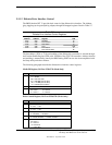
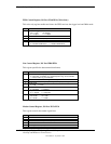
Interrupt Enable Register, I/O Port 3F9h/2F9h
Bits <3..0> of this register are used for enabling interrupt sources. A set bit enables interrupt
generation by the associated source.
Bit Function
7..4 Reserved
3 Modem Status Interrupt Enable (if set) (CTS, DSR, RI, CD)
2 Receiver Line Status Interrupt Enable (if set) (Overrun error,
parity error, framing error, break)
1 Transmitter Holding Register Empty Interrupt Enable (if set)
0 Baud Rate Divisor Interrupt Enable (if set)
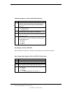
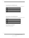
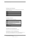
Interrupt ID Register, I/O Port 3FAh/2FAh (Read Only)
This read-only register indicates the serial controller as the source of the interrupt (bit <0>) as
well as the reason (bits <3..1>) for the interrupt. Reading this register clears the interrupt and
sets bit <0>.
Bit Function
7,6 FIFO Enable/Disable
0 = Disabled
1 = Enabled
5,4 Reserved
3..1 Interrupt Source:
000 = Modem status (lowest priority)
001 = Transmitter holding reg. Empty
010 = Received data available
011 = Receiver line status reg.
100,101 = Reserved
110 = Character time-out (highest priority)
111 = Reserved
0 Interrupt Pending (if cleared)


