Chapter 7 Power and Signal Distribution
Compaq Deskpro EN Series of Personal Computers
Desktop and Minitower Form Factors
Third Edition - September 1998
7-8
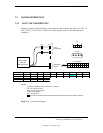
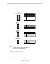
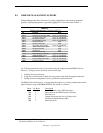
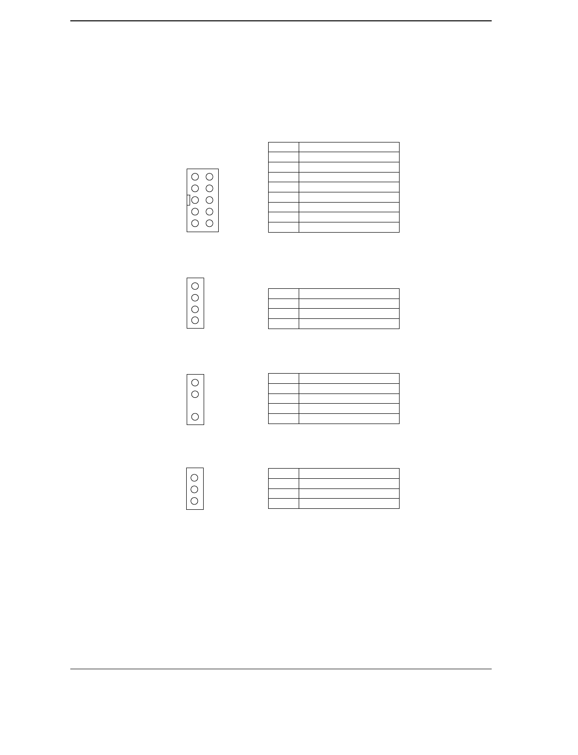
Pins Function
1,3 Cover Lock & 12 VDC
2,3 Cover Unlock & 12 VDC
4 Not connected
5 Power LED (-)
6 HD LED (-)
7 Power LED (+)
8 HD LED (+)
9,10 Power Button
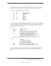
Pins Function
1,3 Signal ground
2 Left Audio Channel
4 Right Audio Channel
Pins Function
1 Fan present sense
2 Fan Power (-)
3Key
4 Fan Power (+)
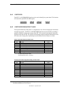
Pins Function
1 +5 AUX
2 Ground
3 WOL signal
NOTE:
No polarity consideration required for cable connection to
header P6 (speaker) or P29 (SCSI HD LED).
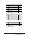
Figure 7–5. Backplane Header Pinouts
Header P5
(Panel LEDs, Pwr Btn)
1
5
7
9
3
2
6
8
10
4
Header P7
(
CD Audio
)
1
3
4
2
Header P8
(
Chassis Fan
)
1
4
2
1
2
3
Header P9
(Wake On LAN)


