


Chapter 3 Processor/Memory Subsystem
Compaq Deskpro EN Series of Personal Computers
Desktop and Minitower Form Factors
Third Edition - September 1998
3-6
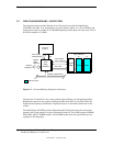
3.2.3 SYSTEM MEMORY
The system board contains three 168-pin DIMM sockets for system memory. This system is
designed for using SDRAM or ECC DIMMs. As shipped from the factory the standard
configuration has 16, 32, or 64 megabytes of memory installed. The system memory is
expandable up to a maximum of 384 megabytes. Single or double-sided DIMMs may be used. In
expanding the standard memory using modules from third party suppliers the following DIMM
type is recommended:
66- or 100-MHz unbuffered RAM supporting CAS latency (CL) 2 or 3
with a data access time (clock-to-data out) of 9.0 ns or less @ CL=2 or CL=3
.
NOTE:
The DIMM speed should compliment the host bus speed of the processor (i.e.,
use 66-MHz DIMMs in a system with a 266/66 processor and 100-MHz DIMMs in a
system with a 350/100 processor). All systems are factory-shipped with 100-MHz
DIMMs.
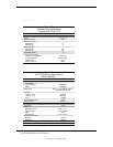
The RAM type and operating parameters are detected during POST by the system BIOS using the
serial presence detect (SPD) method. This method employs an I
2
C bus to communicate with an
EEPROM on each installed DIMM. The EEPROM holds the type and operating parameter data.
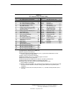
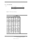
The supported format complies with the JEDEC specification for 128-byte EEPROMs. This
system also provides support for 256-byte EEPROMs to include additional Compaq-added
features such as part number and serial number. The SPD format as supported in this system is
shown in Table 3-3.
The key SPD bytes that BIOS checks for compatibility are 2, 9, 10, 18, 23, and 24.
If BIOS
detects EDO DIMMs a “memory incompatible” message will be displayed and the system
will halt.
If ECC DIMMs are used, all DIMMs installed must be ECC for ECC benefits (error
logging) to be realized.
Once BIOS determines the DIMM type the DRAM speed and CAS latency is checked based on
the following criteria:
Access
from
Bus Speed Cycle Time
Clock
66 MHz 15 ns 9 ns @ 50 pf loading
100 MHz 10 ns 6 ns @ 50 pf loalding
NOTE:
Refer to chapter 8 for a description of the BIOS procedure of interrogating
DIMMs.
Only CAS latencies of 2 or 3 are supported. If DIMMs with unequal CAS latencies are installed
then operation will occur based on the DIMM with the greatest latency.
If an incompatible DIMM is detected the NUM LOCK will blink for a short period of time during
POST and an error message may or may not be displayed before the system hangs.
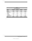
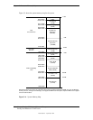
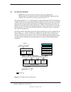
The system memory map is shown in Figure 3-3.