


Technical Reference Guide
Compaq Deskpro EN Series of Personal Computers
Desktop and Minitower Form Factors
Third Edition - September 1998
7-5
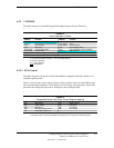
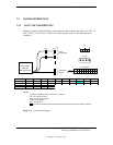
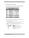
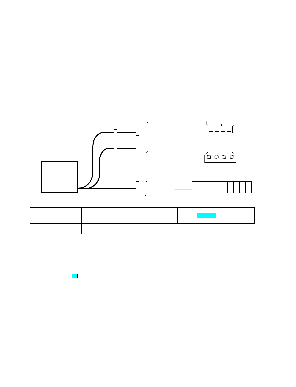
7.3 POWER DISTRIBUTION
7.3.1 3.5/5/12 VDC DISTRIBUTION
The power supply assembly includes a multi-connector cable assembly that routes +3.3 VDC, +5
VDC, -5 VDC, +12 VC, and -12 VDC to the system board as well as to the individual drive
assemblies.
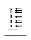
Connector Pin 1 Pin 2 Pin 3 Pin 4 Pin 5 Pin 6 Pin 7 Pin 8 Pin 9 Pin 10
P1 +3.3 +3.3RS RTN +5 RTN +5 RTN Fan Off +5AUX +12
P1 [1] +3.3 -12 RTN PS On RTN RSRTN RTN -5 +5 +5
P3-P5 +12 GND GND +5
P6 +5 GND GND +12
NOTES:
[1] This row represents pins 11-20 of the P1 connector.
All + and - values are VDC
.
RTN = Return (signal ground)
GND = Power ground
RS = Remote sense
= Deviation from ATX standard. PWR GD signal is produced by the south bridge component.
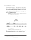
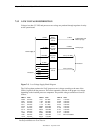
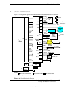
Figure 7–2
. Power Cable Diagram
Power Supply
Assembly
(SP# 334112-001)
Drive
Assemblies
P1
P6
P3
P3
Backplane
Board
1 2 3 4
P3-P5
P6
4 3 2 1
P4
P5
P1 (ATX-type)
1
12 2011
2 5 4 3 7 8 6 9
14
10
13 16 1715 18 19
P2