CY7C63310, CY7C638xx
Document 38-08035 Rev. *K Page 32 of 83
13.0.1 ECO Trim Register
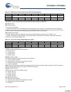
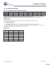
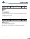
Table 13-2. Voltage Monitor Comparators Register (VLTCMP) [0x1E4] [R]
Bit # 7 6 5 4 3 2 1 0
Field Reserved LVD PPOR
Read/Write – – – – ––R R
Default 0 0 0 0 000 0
This read only register allows reading the current state of the Low-Voltage-Detection and Precision-Power-On-Reset compar-
ators
Bit [7:2]: Reserved
Bit 1: LVD
This bit is set to indicate that the low-voltage-detect comparator has tripped, indicating that the supply voltage has gone below
the trip point set by VM[2:0] (See Table 13-1)
0 = No low-voltage-detect event
1 = A low-voltage-detect has tripped
Bit 0: PPOR
This bit is set to indicate that the precision-power-on-reset comparator has tripped, indicating that the supply voltage is below
the trip point set by PORLEV[1:0]
0 = No precision-power-on-reset event
1 = A precision-power-on-reset event has occurred
Note This register exists in the second bank of IO space. This requires setting the XIO bit in the CPU flags register.
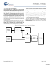
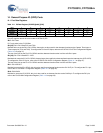
Table 13-3. ECO (ECO_TR) [0x1EB] [R/W]
Bit # 7 6 5 4 3 2 1 0
Field Sleep Duty Cycle [1:0] Reserved
Read/Write R/W R/W – – – – – –
Default 0 0 0 0 000 0
This register controls the ratios (in numbers of 32 kHz clock periods) of “on” time versus “off” time for LVD and POR detection
circuit.
Bit [7:6]: Sleep Duty Cycle [1:0]
0 0 = 1/128 periods of the Internal 32 kHz Low-speed Oscillator
0 1 = 1/512 periods of the Internal 32 kHz Low-speed Oscillator
1 0 = 1/32 periods of the Internal 32 kHz Low-speed Oscillator
1 1 = 1/8 periods of the Internal 32 kHz Low-speed Oscillator
Note This register exists in the second bank of IO space. This requires setting the XIO bit in the CPU flags register.
[+] Feedback [+] Feedback


