


CY7C63310, CY7C638xx
Document 38-08035 Rev. *K Page 44 of 83
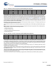
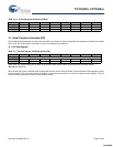
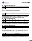
Table 16-3. Timer Capture 0 Rising (TIO0R) [0x22] [R/W]
Bit # 7 6 5 4 3 2 1 0
Field Capture 0 Rising [7:0]
Read/Write R/W R/W R/W R/W R/W R/W R/W R/W
Default 0 0 0 0 000 0
Bit [7:0]: Capture 0 Rising [7:0]
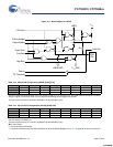
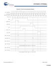
This register holds the value of the Free-running Timer when the last rising edge occurred on the TIO0 input. When Capture 0
is in 8-bit mode, the bits that are stored here are selected by the Prescale [2:0] bits in the Timer Configuration register. When
Capture 0 is in 16-bit mode this register holds the lower order 8 bits of the 16-bit timer.
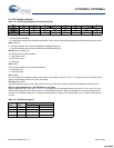
Table 16-4. Timer Capture 1 Rising (TIO1R) [0x23] [R/W]
Bit # 7 6 5 4 3 2 1 0
Field Capture 1 Rising [7:0]
Read/Write R/W R/W R/W R/W R/W R/W R/W R/W
Default 0 0 0 0 000 0
Bit [7:0]: Capture 1 Rising [7:0]
This register holds the value of the Free-running Timer when the last rising edge occurred on the TIO1 input in the 8-bit mode.
The bits that are stored here are selected by the Prescale [2:0] bits in the Timer Configuration register. When Capture 0 is in
16-bit mode this register holds the high order 8 bits of the 16-bit timer from the last Capture 0 rising edge.
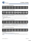
Table 16-5. Timer Capture 0 Falling (TIO0F) [0x24] [R/W]
Bit # 7 6 5 4 3 2 1 0
Field Capture 0 Falling [7:0]
Read/Write R/W R/W R/W R/W R/W R/W R/W R/W
Default 0 0 0 0 000 0
Bit [7:0]: Capture 0 Falling [7:0]
This register holds the value of the Free-running Timer when the last falling edge occurred on the TIO0 input. When Capture 0
is in 8-bit mode, the bits that are stored here are selected by the Prescale [2:0] bits in the Timer Configuration register. When
Capture 0 is in 16-bit mode this register holds the lower order 8 bits of the 16-bit timer.
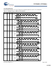
Table 16-6. Timer Capture 1 Falling (TIO1F) [0x25] [R/W]
Bit # 7 6 5 4 3 2 1 0
Field Capture 1 Falling [7:0]
Read/Write R/W R/W R/W R/W R/W R/W R/W R/W
Default 0 0 0 0 000 0
Bit [7:0]: Capture 1Falling [7:0]
This register holds the value of the Free-running Timer when the last falling edge occurred on the TIO1 input in the 8-bit mode.
The bits that are stored here are selected by the Prescale [2:0] bits in the Timer Configuration register. When capture 0 is in
16-bit mode this register holds the high order 8 bits of the 16-bit timer from the last Capture 0 falling edge.
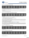
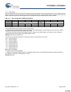
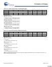
Table 16-7. Programmable Interval Timer Low (PITMRL) [0x26] [R]
Bit # 7 6 5 4 3 2 1 0
Field Prog Interval Timer [7:0]
Read/Write R R R R RRR R
Default 0 0 0 0 000 0
Bit [7:0]: Prog Interval Timer [7:0]
This register holds the low order byte of the 12-bit programmable interval timer. Reading this register causes the high order byte
to be moved into a holding register allowing an automatic read of all 12 bits simultaneously.
[+] Feedback [+] Feedback