Dell PowerConnect 28xx Systems User Guide 25
SFP Ports
The PowerConnect 2824 switch supports two SFP transceivers combo ports, and the PowerConnect 2848
switch supports four SFP transceivers combo ports for various fiber-based modules (1000BASE-SX or
1000BASE-LX). Only one of the two physical connections of a combo port can be used at any time. The
system can switch from the RJ-45 to the SFP (or vice versa) without a system reset. The system
automatically detects the media used on a combo port, and utilizes this information in the control
interfaces.
PowerConnect 2824 switch supports SFP diagnostics. The optical transceiver provides access to a set of
parameters that can be monitored and displayed to the system administrator.
NOTE: If both RJ-45 and SFP ports are present, the SFP port will be the active port, whereas the RJ-45 port will be
disabled and ignored.
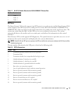
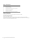
The pin number allocation for the SFP ports is listed in the following table.
6 TxRx 3-
7 TxRx 4+
8 TxRx 4-
Table 2-8. SFP Pin Connections
Pin No Use
1 Transmitter ground (common with receiver ground)
2 Transmitter fault
3 Transmitter disable; laser output disabled on high or open.
4 Module definition 2; data line for serial ID.
5 Module definition 1; clock line for serial ID.
6 Module definition 0; grounded within the module.
7 Rate select; no connection required.
8 Loss of signal indication; logic 0 indicates normal operation.
9 Receiver ground (common with transmitter ground)
10 Receiver ground (common with transmitter ground)
11 Receiver ground (common with transmitter ground)
12 Receiver inverted data out; AC coupled.
13 Receiver non-inverted data out; AC coupled.
14 Receiver ground (common with transmitter ground)
Table 2-7. RJ-45 Pin Number Allocation for 10/100/ 1000BASE-T Ethernet Port
Pin No Function


