


Delta DOP Series HMI Connection Manual|DOP-A/AE/AS Series
Revision January, 2008, Doc. Name: 2007PDD23000007 1-99
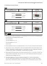
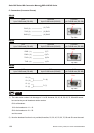
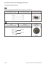
Modbus Hexadecimal Address (Master) --- RTU / ASCII mode Back to Table
A. HMI factory settings
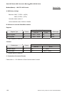
Baud rate: 9600, 7, EVEN, 1. (ASCII)
9600, 8, EVEN, 1. (RTU)
Controller station number: 0.
Control area/status area: RW-0 / RW-10.
NOTE
1) The valid communication address starts from 0 and the format is hexadecimal. So the settable range are
0 to 65535 (i.e. 0 ~ FFFF in hexadecimal format).
2) The difference than “Standard Modbus” communication: (Protocol is the same)
The usage of setting communication address is different.
The range of communication address is different
The “Standard Modbus” communication is in decimal format. The start addresses are 40001, 30001, 1,
10001 and contains 10000 addresses respectively (40001 ~ 50000, 30001 ~ 40000, 1 ~ 10000, 10001 ~
20000).
The Modbus Hexadecimal Address (Master) is in hexadecimal format. The starting addresses are all
from 0 and there is 65536 addressing space (from 0 to FFFF) in each PDU (protocol data unit).
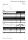
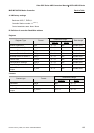
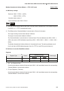
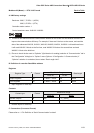
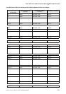
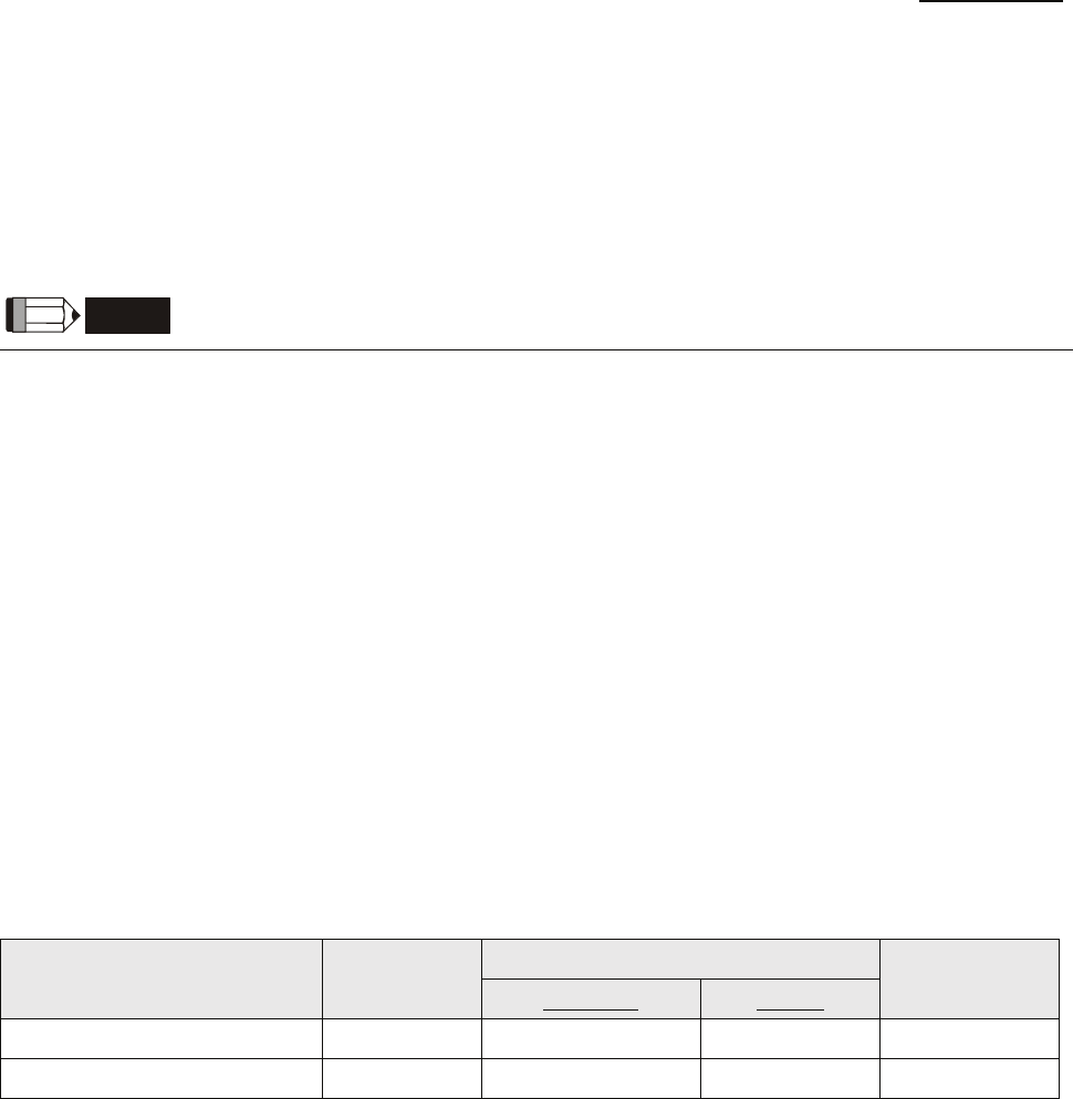
B. Definition of controller Read/Write address
Registers
Read/Write Range
Register Type Format
Word No. Bit No.
Data length
Output Registers RW-n n: 0 ~ FFFF N/A Word
Input Registers R-n n: 0 ~ FFFF N/A Word
¾
RW- : can Read and Write.
Converting the address to decimal format and plus 40001, it will immediately become the corresponding
“Standard Modbus” communication address.
¾
R- (Input Registers) : Read only.
Converting the address to decimal format and plus 30001, it will immediately become the corresponding
“Standard Modbus” communication address.