


Delta DOP Series HMI Connection Manual|DOP-A/AE/AS Series
1-112 Revision January, 2008, Doc. Name: 2007PDD23000007
For example, if setting the starting address as RW900 and the data size is Double Word, the read/write
value will be a Double Word which contains RW900(low word) and RW901(high word).
In actual application case, if the user sets the data size of RW-n, DW-n as Word, there is no data order
reverse problem. However, if the user sets the data size of RW-n, DW-n as Double Word, as this
controller use "Big Endian" architecture which means that the high word of the number is stored in
memory at the lowest address, and the low word at the highest address (such as Motorola processors
(those used in Mac's) use "Big Endian" byte order), a data order reverse problem will occur.
3) The data size of RD-n, DD-n is defined as Double Word in DOP series HMI and every two data
addresses is regarded as an individual Double Word address. The data order use "Big Endian"
architecture (see the meaning above).
For example, if setting the starting address as RD900 and the data size is Double Word, the read/write
value will be a Double Word which contains RW900(high word) and RW901(low word).
In actual application case, if the users set the data size of RD-n, DD-n as Double Word, there is no data
order reverse problem and the data display on HMI and the controller will be the same. However, if the
users set the data size of RD-n, DD-n as Word, only the low word will display and the high word will be
set to 0 automatically. For example, if setting the starting address as RD900 and the data size is Word,
only the value of RD901(low word) will display. If the write value is 100 at this time, DOP series HMI will
set the value of RD901(high word) to 0 and write the value 100 into RD901(low word).
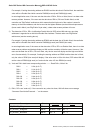
4) X-nb and DW-n both have corresponding relation -------- Read DW-n, Write X-nb
DW-0 — X-0b, (b=0~F)
DW-1 — X-1b, (b=0~F)
DW-2 — X-2b, (b=0~F)
DW-4 — X-3b, (b=0~F)
DW-104 — X-4b, (b=0~F)
DW-105 — X-5b, (b=0~F)
DW-106 — X-6b, (b=0~F)
DW-107 — X-7b, (b=0~F)
DW-108 — X-8b, (b=0~F)
5) DW-n, DD-n are “read only”. If the users write any value into them, HMI will show error message
“Command Can Not be Executed…. ” on the screen.
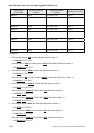
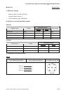
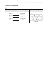
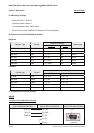
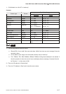
Contacts
Contact type Format Word No. Bit No.
BIT_DEVICE_ RRegister RB-nb n: 0 ~ 3999 b:0 ~ F
BIT_DEVICE_ RRegister RB-nb n: 8000 ~ 9999 b:0 ~ F
BIT_DEVICE_ BitControl XB-nb n:0 ~ 8 b:0 ~ F