


Delta DOP Series HMI Connection Manual|DOP-A/AE/AS Series
Revision January, 2008, Doc. Name: 2007PDD23000007 1-1
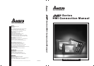
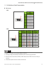
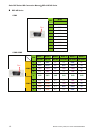
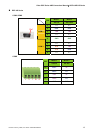
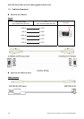
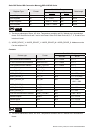
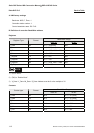
1.1 Pin Definition of Serial Communication
DOP-A Series
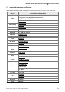
COM1
Mode
PIN
RS-232
1 N.C
2 RXD
3 TXD
4 N.C
5 GND
6 N.C
7 RTS
8 CTS
9 N.C
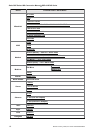
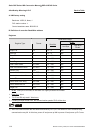
COM2
Mode 1 Mode 2 Mode 3
PIN
RS-232 RS-422 RS-485
1 N.C RXD- D-
2 RXD RXD+ D+
3 TXD TXD+ D+
4 N.C TXD- D-
5 GND GND GND
6 N.C RTS- N.C
7 RTS RTS+ N.C
8 CTS CTS+ N.C
9 N.C CTS- N.C
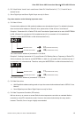
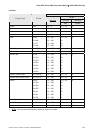
NOTE
1) Mode 3 is for RS-485. Pin 2 & 3 are D+ and pin 1 & 4 are D
-
.
2) Grounding is highly recommended if RS-485 & RS-422 are used for long transmission.
3) DO NOT connect Frame Ground (FGND) to GND. Please connect FGND to the outer covering of
connector.
4) Transmission speed is relevant to distance and baud rate.
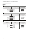
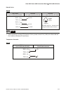
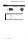
Pin1
Pin1