


Delta DOP Series HMI Connection Manual|DOP-A/AE/AS Series
Revision January, 2008, Doc. Name: 2007PDD23000007 1-89
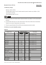
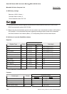
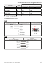
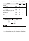
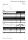
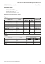
Read/Write Range
Contact type Format
Word No. Bit No.
Alarm reset (ARST)
(cmd: NA/82,00)
(NOTE 1)
ARSTb N/A b: 0
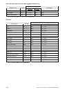
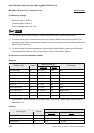
Turn off the external input signals (DI) (OFDI)
(cmd: NA/90,00)
(NOTE 1)
OFDIb N/A b: 0
Changes the external output signals (DO) (CHDO)
(cmd: NA/90,03)
(NOTE 1)
CHDOb N/A b: 0
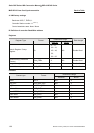
Enable the disabled external input signals (ENDI)
(cmd: NA/90,10)
(NOTE 1)
ENDIb N/A b: 0
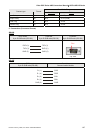
Enable the disabled external output signals (ENDO)
(cmd: NA/90,13)
(NOTE 1)
ENDOb N/A b: 0
Clear the time constant of acceleration in test
operation mode (TCLR)
(cmd: NA/A0,12)
(NOTE 1)
TCLRb N/A b: 0
Temporary stop of position mode in test operation
(TSTP)
(cmd: NA/A0,15)
(NOTE 1)
TSTPb N/A b: 0
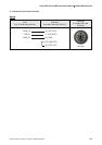
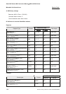
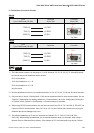
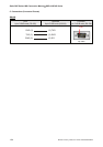
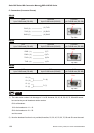
C. Connections (Connector Pinouts)
RS-232
DOP Series
9 pin D-SUB male (RS-232)
Controller
20 pin CN3
GND (5)
GND (1)
GND (11)
RXD (2
)
TXD ( 12
)
TXD (3)
RXD (2)
NOTE
1) Read / Write Limit
This communication protocol uses devices to simulate the operation of Servo, so there is a limit for the
device to read and write the command. In the column of register type and contact type, the string of
characters after “cmd:” indicates the corresponding Servo command that the device will read and write.
For example, the string of characters after “cmd:” of the register, Status display is 01,8n/NA. It means
that the device can read it but cannot write it. One more example, the string of characters after “cmd:” of
the Operation mode selection (OP) is N/A/8B,00. It means that the device can write it but cannot read it.