


Delta DOP Series HMI Connection Manual|DOP-A/AE/AS Series
1-40 Revision January, 2008, Doc. Name: 2007PDD23000007
Jetter Nano Series PLC Back to Table
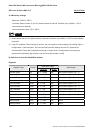
A. HMI factory settings
Baud rate: 9600, 8, EVEN, 1 (RS-232).
Controller station number: 0. (no PLC station number in protocol, therefore, only 1(HMI) to 1 (PLC)
communication is allowed.)
Control area/status area: WR0 / WR10.
NOTE
1) Please notice that no PLC station number in protocol, therefore, only 1(HMI) to 1 (PLC) communication
is allowed.
2) Only 1 Bit or 1 Word can be transferred for each communication.
3) In general, each register occupies max. 24 Bits. However, some registers occupies 8 Bits only.
4) Because the initial time of this controller is longer, it is recommended to set HMI startup delay time
(Recommended time is 10 seconds).
5) When the register R is used for Double Word device, please set its format as signed format. (The default
format in Screen Editor is signed format)
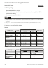
B. Definition of controller Read/Write address
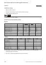
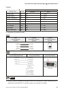
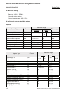
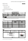
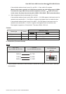
Registers
Read/Write Range
Register Type Format
Word No. Bit No.
Data
Length
16 Bits Register WRn n: 0 ~ 32767 N/A 16 Bits
32 Bits Register Rn n: 0 ~ 32767 N/A 24 Bits
Only the first 16 bits are used for WRn registers.
Only the first 24 bits are used for Rn registers, the highest 8 bits (Bit 24 ~ 31) are set to 0 by default setting.
(24-bit Integer : If in decimal format, the range is -8388608 ~ +8388607. If in hexadecimal format, the range
is 0x000000 ~ 0xFFFFFF.)
NOTE
1) The difference between WRn and Rn:
y When using devices that the data length is in Word, only Bit 0 ~ 15 are valid for both of WRn and
Rn registers.
y When using devices that the data length is in Double Word,
if the read/write address format is set to WRn, the Bit 0 ~ 15 of WRn register is the low word of a
read/write value, the Bit 0 ~ 15 of WRn+1 register is the high word of a read/write value.