


Delta DOP Series HMI Connection Manual|DOP-A/AE/AS Series
Revision January, 2008, Doc. Name: 2007PDD23000007 1-127
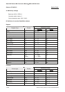
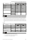
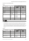
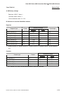
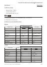
B. Definition of controller Read/Write address
Register
Read/Write Range
Register Type Format
Word No. Bit No.
Input Image IWn n: 0 ~ 65534 N/A
Input Image IDn n: 0 ~ 65532 N/A
Output Image QWn n: 0 ~ 65534 N/A
Output Image QDn n: 0 ~ 65532 N/A
Internal Bits MWn n: 0 ~ 65534 N/A
Internal Bits MDn n: 0 ~ 65532 N/A
Data Area DBm.DBWn n: 0 ~ 65534 m: 1 ~ 255 (Note 1)
DBm.DBDn n: 0 ~ 65532 m: 1 ~ 255 (Note 1)
Data Area (DB10) DBWn n: 0 ~ 65534 N/A
DBDn n: 0 ~ 65532 N/A
VWn n: 0 ~ 65534 N/A
VDn n: 0 ~ 65532 N/A
Timer Tn n: 0 ~ 65535 N/A
Counter Cn n: 0 ~ 65535 N/A
NOTE
1) High Byte of Bit No.
¾
The valid digit number of the value for the T(Timer) and C(Counter) is 3-digits only. Therefore, please
enter a 3-digit number. If entering a number that exceeds 3 digits, only the first 3 digits are valid (decimal
format). The other digits of the value for the T(Timer) will be replaced as 0 and the other digits of the
value for the C(Counter) will be abandoned. For example, assume that the users enter the value “12345”,
the actual write value for the T(Timer) will be “12300” and the actual write value for the C(Counter) will
be “123”.
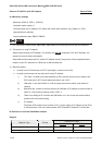
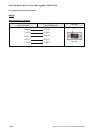
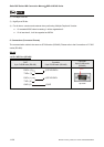
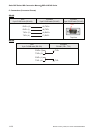
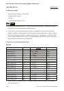
Contacts
Read/Write Range
Contact type Format
Word No. Bit No.
Input Image In.b n: 0 ~ 65535 b: 0 ~ 7 (Note 2)
Output Image Qn.b n: 0 ~ 65535 b: 0 ~ 7 (Note 2)
Internal Bit Mn.b n: 0 ~ 65535 b: 0 ~ 7 (Note 2)
Data Area Bit DBm.DBXn.b n: 0 ~ 65535 b: 0 ~ 7 (Note 2)
m = 1 ~ 255 (Note 3)
Data Area Bit (DB 10) DBXn.b n: 0 ~ 65535 b: 0 ~ 7 (Note 2)
Vn.b n: 0 ~ 65535 b: 0 ~ 7 (Note 2)