


Delta DOP Series HMI Connection Manual|DOP-A/AE/AS Series
Revision January, 2008, Doc. Name: 2007PDD23000007 1-91
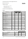
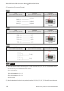
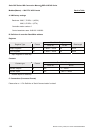
C. Connections (Connector Pinouts)
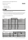
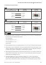
RS-232
DOP
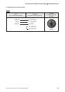
9 pin D-SUB male (RS-232)
Controller
20 pin CN3
Controller
20 pin CN3
RXD (2)
(3) TXD
TXD (3)
GND (5)
(2) RXD
(5) SG
Top View
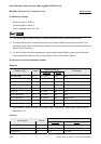
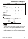
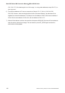
RS-485
DOP
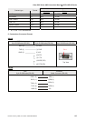
9 pin D-SUB male (RS-485)
Controller Controller
RXD (2)
(3) TXD
TXD (3)
GND (5)
(2) RXD
(5) SG
Top View
NOTE
1) The valid station number is in the range of 11 to 99. However, 20, 30, 40, 50, 60, 70, 80 and 90 cannot
be used as they are all broadcast station number.
00 for all broadcast
10 for the broadcast to 11 ~ 19
20 for the broadcast to 21 ~ 29
and vise versa.
2) Now the broadcast function is not provided, therefore, 20, 30, 40, 50, 60, 70, 80 and 90 cannot be used.
3) Only one data (1 Word/ 1 Double Word / 1 Bit) can be read and written for each communication. So, the
“Optimize” (Optimization for reading) selection in “Communication” tab in the “Configuration” dialog box
in “Options” menu (Options Æ Configuration Æ Communication) is cancelled.
4) When using RS-232 communication, the user only can use 3 pins (Pin 2, Pin 3 and Pin 5). DO NOT use
5 pins for RS-232 communication. Also, Pin 9 is for +5V. Do not confuse and connect to the wrong pin;
otherwise the serious damage may occur.
5) The effective addresses of Cn are not consecutive (5 blocks: C0~17, C40~41, C45~C48, C50,
C90~C92). When setting the addresses, do not exceed the block range. For example, when using a
Numeric Entry or Character Entry element, if the address is C15, the data length only can be 6 Words
Pin1
Pin1