


Delta DOP Series HMI Connection Manual|DOP-A/AE/AS Series
Revision January, 2008, Doc. Name: 2007PDD23000007 1-23
Copley Servo (Stepnet Protocol) Back to Table
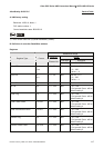
A. HMI factory setting
Baud rate: 9600, 8, None, 1.
PLC station number: 0.
Control area/status area: None.
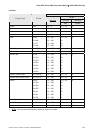
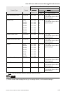
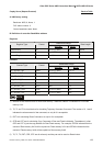
B. Definition of controller Read/Write address
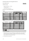
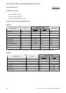
Registers
Read/Write Range
Register Type Format
Word No. Bit No.
Data Length
RAM memory Rn n: 00-FF (Hex) N/A DWord
Flash memory Fn n: 00-FF (Hex) N/A DWord
Internal Register IRn n: 0-31 N/A Word
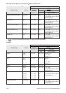
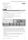
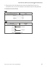
Contacts
Read/Write Range
Contact Type Format
Word No. Bit No.
BIT_DEVICE_RB RBn.b n: 00-FF (Hex) b: 0-31
BIT_DEVICE_FB FBn.b n: 00-FF (Hex) b: 0-31
BIT_DEVICE_T0 T0n N/A n: 0
BIT_DEVICE_T1 T1n N/A n: 0
BIT_DEVICE_T2 T2n N/A n: 0
BIT_DEVICE_RST RSTn N/A n: 0
BIT_DEVICE_CPR CPRn n: 00-FF (Hex) N/A
BIT_DEVICE_CPF CPFn n: 00-FF (Hex) N/A
NOTE
1) RB and FB are the bit access of Ram/Flash memory. Therefore, RB0x21.14 indicates bit 14 of Ram
memory 0x21.
2) T0, T1 and T2 is virtual device for simulating Trajectory Generator Command. The number of 0, 1 and 2
indicates the subcommand of that command, so only bit 0 is acceptable.
3) RST is for simulating Reset Command, so only bit 0 is acceptable.
4) CPR and CPF are for simulating Copy Command of Ram and Flash individually. The address (n) after
CPR and CPF is just the copy address for Ram/Flash memory. For example, CPRCA indicates that the
content of Ram memory 0xCA will be copied into Flash memory 0xCA and CPFA6 indicates that the
content of Flash memory 0xA6 will be copied into Ram memory 0xA6.
5) T0, T1, T2, RST, CPR, CPF are all write-only and they can not be used on Reset button.