


Delta DOP Series HMI Connection Manual|DOP-A/AE/AS Series
1-14 Revision January, 2008, Doc. Name: 2007PDD23000007
AllenBradley MicroLogix PLC Back to Table
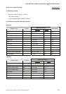
A. HMI factory setting
Baud rate: 19200, 8, None, 1.
PLC station number: 1.
Control area/status area: B3:0/B3:10.
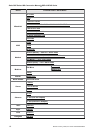
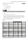
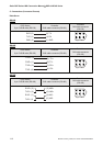
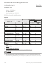
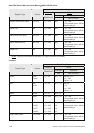
B. Definition of controller Read/Write address
Registers
Read/Write Range
Bit No.
Register Type Format
Word No.
Low Byte
High Byte
File No.
Output File O:n n: 0 ~ 3 N/A 0
Input File I:n n: 0 ~ 3 N/A 1
Status File S2:n n: 0 ~ 65 N/A 2
Bit File B3:n n: 0 ~ 255 N/A 3
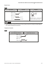
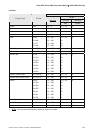
Timer Flag T4:n n: 0 ~ 255 N/A 4
Timer Preset Value T4:n.PRE n: 0 ~ 255 N/A 4
Timer Accumulator Value T4:n.ACC n: 0 ~ 255 N/A 4
Counter Flag C5:n n: 0 ~ 255 N/A 5
Counter Preset Value C5:n.PRE n: 0 ~ 255 N/A 5
Counter Accumulator Value C5:n.ACC n: 0 ~ 255 N/A 5
Control File R6:n n: 0 ~ 255 N/A 6
Control Size of Bit Array R6:n.LEN n: 0 ~ 255 N/A 6
Control Reserved File R6:n.POS n: 0 ~ 255 N/A 6
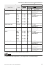
Integer File N7:n n: 0 ~ 255 N/A 7
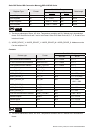
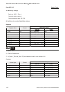
¾
Bit No
: Low byte is not used, so the value is 0. High byte stores file number.
¾
Data Size
: Word.
¾
T4, C5 and R6 only read 1 Word once.
¾
If reading multiple Words once, the communication speed of PLC will be slow.
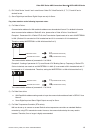
NOTE
1) After last communication data has been memorized by PLC (PLC will send 0x10 0x05 consecutively),
communication may fail. At this time, power off and power up HMI or power off and power up PLC once.