


Delta DOP Series HMI Connection Manual|DOP-A/AE/AS Series
1-72 Revision January, 2008, Doc. Name: 2007PDD23000007
Mitsubishi FX/FX2N PLC Back to Table
A. HMI factory settings
Baud rate: 9600, 7, EVEN, 1.
Controller Station number: 0. (no PLC station number in protocol, therefore, only 1(HMI) to 1 (PLC)
communication is allowed.)
Control area/status area: D0 / D10.
NOTE
1) If connecting to Mitsubishi FXxN series PLC, the user can use both FX2N and FX series communication
protocol.
2) If connecting to Mitsubishi FX series PLC, the user can only use FX series communication protocol.
3) Some registers of Mitsubishi PLCs are “read only”, however, when you write these “read only” registers,
PLCs will not report any communication error to HMI and this will cause HMI errors. Please be aware of
this when editing PLC program (this normally occurs when using FX series protocol when connecting to
a FXxN series PLC).
4) If connecting to Mitsubishi FXxN series PLC, it is recommended for the user to use FX2N protocol.
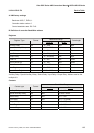
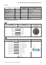
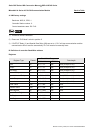
B. Definition of controller Read/Write address
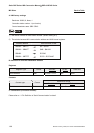
Registers
Read/Write Range
Register Type Format
Word No. Bit No.
Data length
Auxiliary Relay Mn n: 0 ~ 3064 N/A Byte
Special Auxiliary Relay Mn n: 8000 ~ 8248 N/A Byte
Status Relay Sn n: 0 ~ 992 N/A Byte
Input Relay Xn n: 0 ~ 360(octal) N/A Byte
Output Relay Yn n: 0 ~ 360(octal) N/A Byte
Timer PV Tn n: 0 ~ 255 N/A Word
16-bit Counter PV Cn n: 0 ~ 199 N/A Word
32-bit Counter PV Cn n: 200 ~ 255 N/A Double Word
Data Register Dn n: 0 ~ 7999 N/A Word
Special Data Register Dn n: 8000 ~ 8255 N/A Word
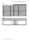
¾
Auxiliary Relay/ Special Auxiliary Relay/ Status Relay/ Input Relay /Output Relay: Address must be the
multiple of 8.