


Delta DOP Series HMI Connection Manual|DOP-A/AE/AS Series
1-76 Revision January, 2008, Doc. Name: 2007PDD23000007
Mitsubishi A Series AJ71UC24 Communication Module Back to Table
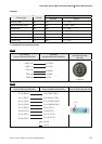
A. HMI factory settings
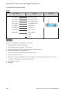
Baud rate: 9600, 8, ODD, 1.
Controller Station number: 0.
Control area/status area: D0 / D10.
NOTE
1) This driver utilizes CheckSum.
2) Please set “PLC Mode” switch to position 5.
3) If OUTPUT Relay (Y) and Special Data Relay (SM) are set to 1, PLC will stop communication and the
communication will not recover automatically. PLC will need to be manually reset.
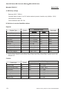
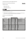
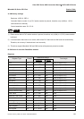
B. Definition of controller Read/Write address
Registers
Read/Write Range
Register Type Format
Word No. Bit No.
Data length
Input Xn n: 0 ~ 7FF N/A Word (multiple of 16)
Output Yn n: 0 ~ 7FF N/A Word (multiple of 16)
Link Relay Bn n: 0 ~ FFF N/A Word (multiple of 16)
Internal Relay Mn n: 0 ~ 8191 N/A Word (multiple of 16)
Special Internal Relay SMn n: 9000 ~ 9255 N/A Word (9000 + multiple of 16)
Latch Relay Ln n: 0 ~ 2047 N/A Word (multiple of 16)
Annunciator Fn n: 0 ~ 2047 N/A Word (multiple of 16)
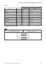
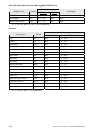
Timer Value TNn n: 0 ~ 999 N/A Word
Counter Value CNn n: 0 ~ 999 N/A Word
Data Register Dn n: 0 ~ 8191 N/A Word
Special Data Register SDn n: 9000 ~ 9255 N/A Word
File Register Rn n: 0 ~ 8191 N/A Word
Link Register Wn n: 0 ~ FFF N/A Word