


Chapter 3 Creating and Editing Screens
3-102 Revision May, 2010
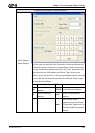
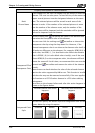
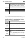
3.8.2.3 Set Value Button
Property Description of Set Value Buttons
After pressing this button on the screen, a system built-in numeric keypad (TEN-KEY)
will show up and the user can use it to input the setting value directly. When ENTER key
is pressed, HMI will send the input setting value to PLC corresponding register. The
maximum and minimum input setting values are all user-defined. The user can also
specify the trigger mode to trigger the designated PLC address before or after writing
the setting value.
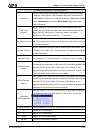
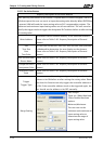
Write Address
The address can be internal memory or the controller address.
(Please refer to Table 3-8-2 Property Description of General
Buttons.)
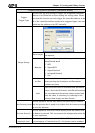
Text
Text Size
Font
Text Color
The user can set the text, text size, font and text color provided
by Windows® to determine the text display on the element
(Please refer to Table 3-8-2 Property Description of General
Buttons.)
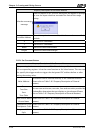
Bank (Picture Bank)
Picture Name
(Please refer to Table 3-8-2 Property Description of General
Buttons.)
Transparent Effect
Transparent Color
(Please refer to Table 3-8-2 Property Description of General
Buttons.)
Foreground Color
Style
(Please refer to Table 3-8-2 Property Description of General
Buttons.)
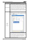
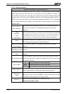
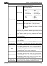
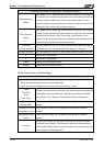
Trigger
Trigger Type
The user can use this setting to trigger the designated controller
address to be ON before or after writing the setting value. Please
note that this function can only trigger the controller address to
be ON. If the controller address needs to be triggered again, the
user should set the address to be OFF manually.
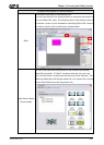
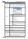
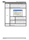
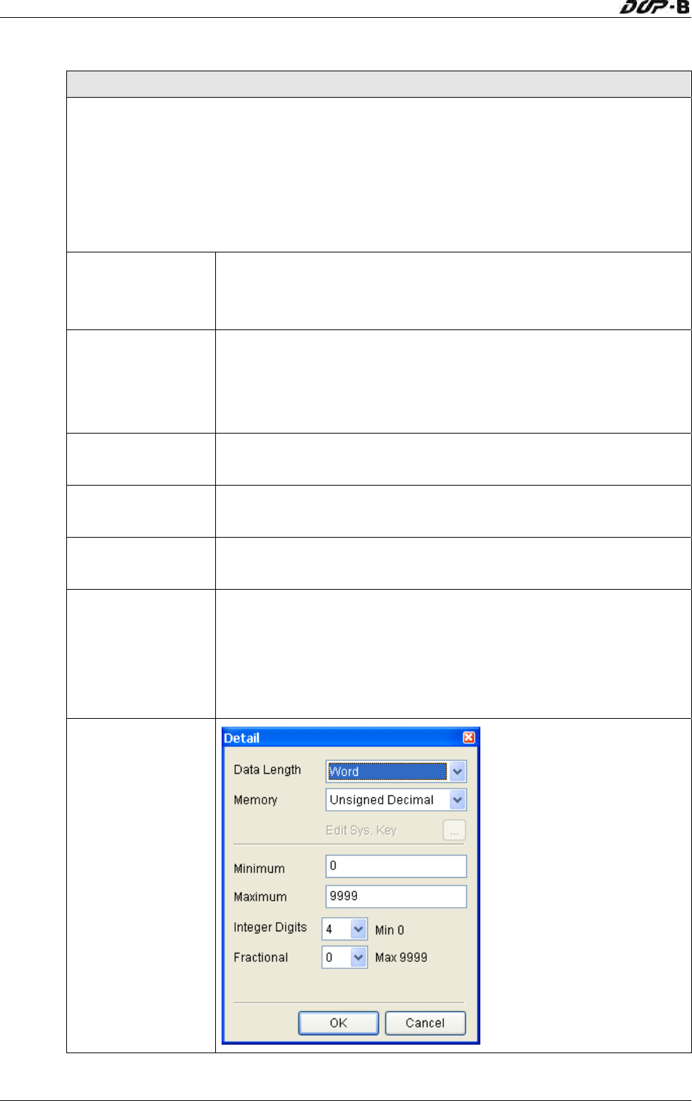
Range Setting
Data Length:
There are 16bits Word and
32bits Double Word two
options.
Minimum/Maximum:
The user can set the
minimum and maximum of
input setting value to
determine the range of
input setting value.