


Chapter 3 Creating and Editing Screens
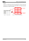
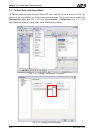
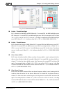
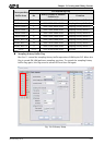
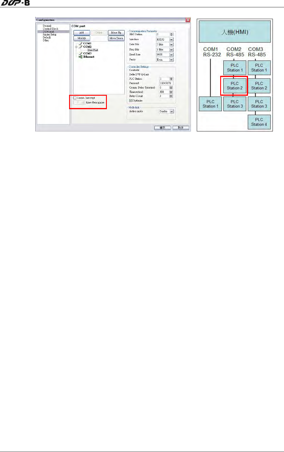
Fig. 3-4-3 Communication tab Fig. 3-4-4 PLC Connections
Communication retry times
is 3 times
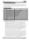
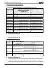
Enable / Disable Backlight
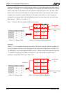
Bit 1 controls the backlight of HMI. When bit 1 is turned ON, the HMI backlight turns
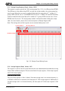
OFF. When bit 1 is turned OFF, the HMI backlight turns ON. For example (refer to Table
3-4-1), if D1 is set to 2 or $16.1 is set to 1, this flag is enabled and the HMI backlight
turns OFF. When D1 = 2, it indicates that Bit 1 of D1 is 1(0000 0000 0000 0010).
Enable / Disable Buzzer
Bit 2 controls the buzzer of HMI. When bit 2 is turned ON, the HMI buzzer turns OFF.
When bit 2 is turned OFF, the HMI buzzer turns ON. For example (refer to Table 3-4-1),
if D1 is set to 4 or $16.2 is set to 1, the HMI buzzer turns ON. At this time, if an alarm
occurs, it will sound. When D1 = 4, it indicates that Bit 2 of D1 is 1 (0000 0000 0000
0100).
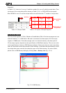
Clear Alarm Buffer
Bit 3 clears the alarm buffer. When an alarm history table is used, setting this bit is
able to clear all data inside of that table. When bit 3 is turned ON, the alarm buffer is
cleared. To clear the alarm buffer again, this flag must be turned OFF and then ON
again. For example (refer to Table 3-4-1), if D1 is set to 8 or $16.3 is set to 1, this flag
is turned ON and the alarm buffer will be cleared. When D1 = 8, it indicates that Bit 3
of D1 is 1 (0000 0000 0000 1000).
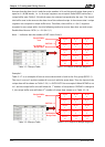
Clear Alarm Counter
Bit 4 clears the alarm counter. When an alarm frequency table is used, setting this bit
is able to clear the values for the alarms. When bit 4 is turned ON, the alarm counter is
cleared. To clear the alarm counter again, this flag must be turned OFF and then ON
again. For example (refer to Table 3-4-1), if D1 is set to 16 or $16.4 is set to 1, this flag
is turned ON and the alarm counter will be cleared. When D1 = 16, it indicates that Bit
4 of D1 is 1 (0000 0000 0001 0000).
Revision May, 2010 3-27