


Chapter 3 Creating and Editing Screens
Screen Number Designation Register (SNIR)
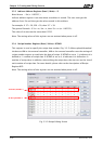
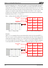
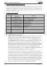
To use this register, write a value of the screen number that the user desires to have
displayed into this register; then HMI will change to that screen. For example (refer to
Table 3-4-1), if set D0 or $15.0 to 1, HMI will change to the 1st screen. If set D0 or $15.0 to
7, HMI will change to 7th screen.
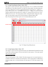
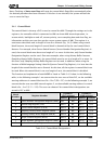
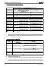
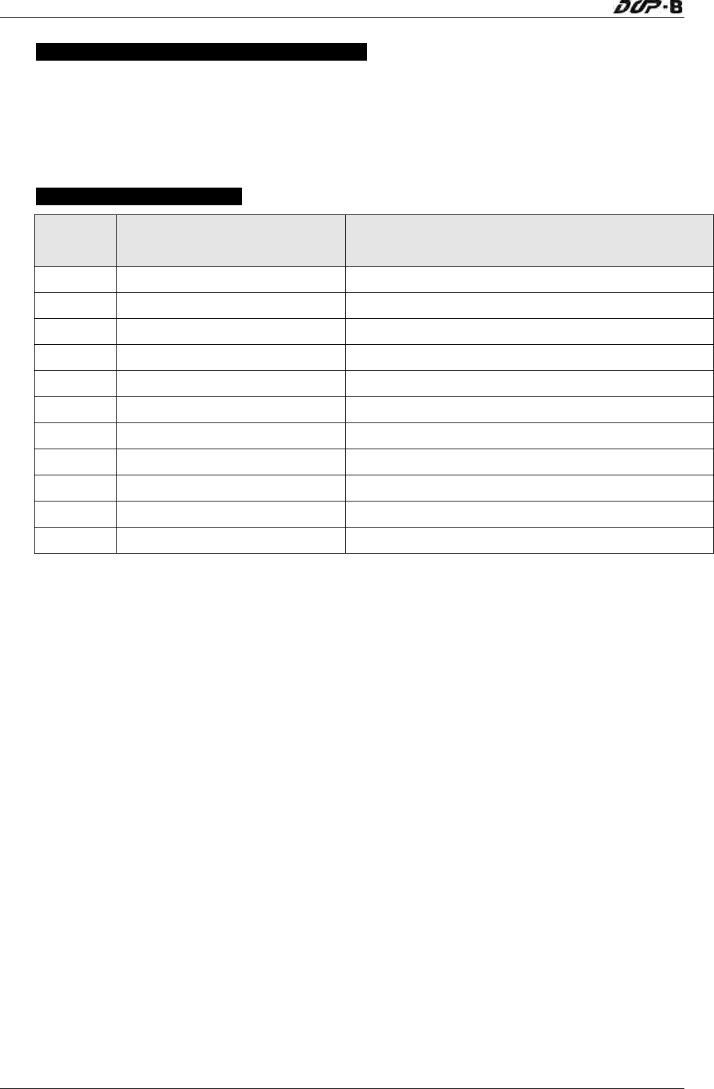
Control Flag Register (CFR)
Bit
Binary Display of Relative
Position (x)
Function
0 0000 0000 0000 000x Enable / Disable Communication
1 0000 0000 0000 00x0 Enable / Disable Backlight
2 0000 0000 0000 0x00 Enable / Disable Buzzer
3 0000 0000 0000 x000 Clear Alarm Buffer
4 0000 0000 000x 0000 Clear Alarm Counter
5 0000 0000 00x0 0000 Update USB Data
6-7 0000 0000 xx00 0000 Reserved
8 0000 000x 0000 0000 Set User Security Level (Level 1)
9 0000 00x0 0000 0000 Set User Security Level (Level 2)
10 0000 0x00 0000 0000 Set User Security Level (Level 4)
11-15 xxxx x000 0000 0000 Reserved
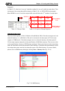
Enable / Disable Communication
Bit 0 controls the HMI communication. When bit 0 is turned ON, HMI communication is
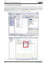
disabled. When bit 0 is turned OFF, HMI communication is enabled. By checking
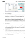
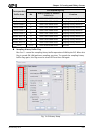
Communication Interrupt check box (Fig. 3-4-3) under the Communication tab of
the Configuration dialog box when communication between one certain PLC is lost
this bit will be turned ON and disable the communication automatically and the
communication fault message will not display (this will not affect the communications
between other PLCs). Then, the user can clear it to enable the communication again. If
this check box is not checked, this flag is disabled (To disable and enable the
communication manually, the user can use OPENCOM/CLOSECOM macro commands.
For more details on macro commands, please refer to section 3.14)
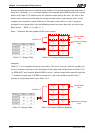
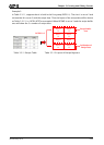
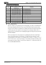
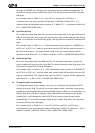
For example (refer to Table 3-4-1 and Fig. 3-4-4), if the PLC which is connected via
COM2 port has communication error and communication retry time has reached three
times, HMI will disable the communication between that PCL automatically (but will
not disable the communication between other PLCs) and will not show communication
errors. At this time, if D1 or $16.0 is set to 0, i.e. the communication flag is turned
OFF, the communication will be enabled again and HMI will communicate with that
PLC again. If the communication is lost for three times, this flag will be ON again.
When D1=0, it indicates that Bit 0 of D1 is 0 (0000 0000 0000 0000).
3-26 Revision May, 2010