


Chapter 3 Creating and Editing Screens
3-198 Revision May, 2010
3.8.15.4 Polygon
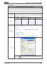
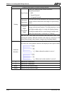
Property Description of Polygon Drawing Element
Left-click the mouse to determine each node of the polygon graphic element. The user
can click where the user wants to place the first node and drag the mouse across work
place on the screen until the next node is decided and left-click the mouse again to
determine the position of the next node. Repeat the above action until the polygon is
the size that the user wants. Then, right-click the mouse the mouse to finish. When
selecting this polygon graphic element, the user can see a rectangle range and this is
designed for the user to move and adjust the polygon more quickly and conveniently.
Changing the size of the rectangle range is changing the size of circle graphic element
directly. The range out of the circle graphic element itself will be displayed in
transparent color. There is a “Transparent” option in the element property table. Once
Yes is selected, the element will display only with the border and there is no color in
the element. If there is any other element under this circle graphic element, it will
show up and can be viewed on the screen.
Curve Color It is used to set the line color of the polygon graphic element.
Foreground Color
It is used to set the display color of the polygon graphic element.
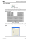
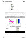
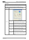
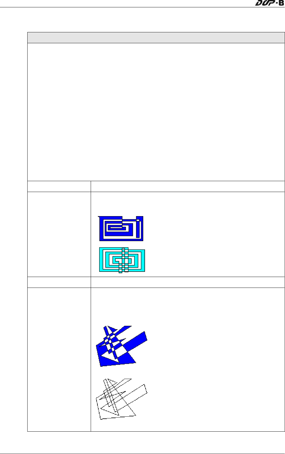
Please refer to the figures below:
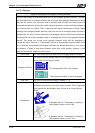
The foreground color is set to blue.
The foreground color is set to turquoise.
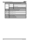
Line Size The unit is Pixel and the range is within 1 ~ 8.
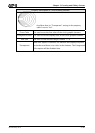
Transparent
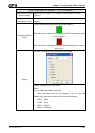
When this option is selected, the element will display only with
the border and there is no color in the element. The Foreground
Color option will be disabled also. Please refer to the figures
below:
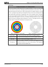
A polygon that its “Transparent” setting in
the property table is set to “No”.
A polygon that its “Transparent” setting in
the property table is set to “Yes”.