


Chapter 3 Creating and Editing Screens
Revision May, 2010 3-37
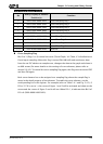
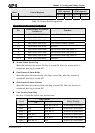
Example 1
(PLC register)
Example 2
(HMI register)
Word Control Register
Address
Example Address
Example
7 General Control Status Register 2 (GCSR2) Dm+7
D17 $m+7
$32
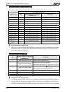
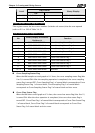
Table 3-4-2 Status Block Designations
General Control Status Register (GCSR)
Bit
Binary Display of Relative
Position (x)
Function
0 0000 0000 0000 000x Screen Switch Status Flag
1-2 0000 0000 0000 0xx0 Reserved
3 0000 0000 0000 x000 Clear Status of Alarm Buffer
4 0000 0000 000x 0000 Clear Status of Alarm Counter
5-7 0000 0000 xxx0 0000 Reserved
8 0000 000x 0000 0000 User Security Level Flag (Level 1)
9 0000 00x0 0000 0000 User Security Level Flag (Level 2)
10 0000 0x00 0000 0000 User Security Level Flag (Level 4)
11-15 xxxx x000 0000 0000 Reserved
Screen Switch Status Flag
When HMI switches the screen, this flag is turned ON. After the screen switch is
completed, this flag is turned OFF.
Clear Status of Alarm Buffer
When HMI clears the alarm buffer, this flag is turned ON. After this function is
completed, this flag is turned OFF.
Clear Status of Alarm Counter
When HMI clears the alarm counter, this flag is turned ON. After this function is
completed, this flag is turned OFF.
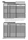
User Security Level Flag
Bits 8 to 10 hold the current user security level.
Flag Control
Level
ON
Binary Display
Level 0 Bit 8, Bit 9, Bit 10 0000 0000 0000 0000
Level 1 Bit 8 Bit 9, Bit 10 0000 0001 0000 0000
Level 2 Bit 9 Bit 8, Bit 10 0000 0010 0000 0000
Level 3 Bit 8, Bit 9 Bit 10 0000 0011 0000 0000
Level 4 Bit 10 Bit 8, Bit 9 0000 0100 0000 0000
Level 5 Bit 8, Bit 10 Bit 9 0000 0101 0000 0000