


Chapter 5 System Menu
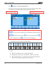
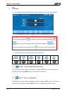
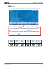
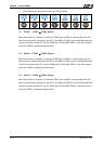
Cross Reference of Function Keys and Screen Icons
1 2
1 3
2 1
LEFT
RIGHT
ENTER
BACK
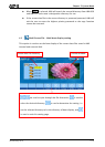
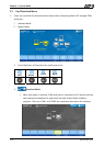
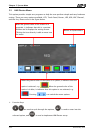
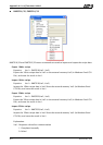
2.1 Mode 1 – COM1 COM2 Bypass
When this mode is selected, it indicates COM2 port of HMI is connected to the PLC,
the user can transfer the data in the PC to the HMI via COM1 port of the HMI and then
transfer the data to the PLC via the COM2 port of the HMI (COM1 is the data source
port and COM2 is the data transfer port).
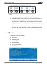
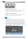
2.2 Mode 2 – COM1 COM3 Bypass
When this mode is selected, it indicates COM3 port of HMI is connected to the PLC,
the user can transfer the data in the PC to the HMI via COM1 port of the HMI and then
transfer the data to the PLC via the COM3 port of the HMI (COM1 is the data source
port and COM3 is the data transfer port).
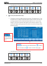
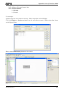
2.3 Mode 3 – COM2 COM1 Bypass
When this mode is selected, it indicates COM1 port of HMI is connected to the PLC,
the user can transfer the data in the PC to the HMI via COM2 port of the HMI and then
transfer the data to the PLC via the COM1 port of the HMI (COM2 is the data source
port and COM1 is the data transfer port).
5-20 Revision May, 2010