


Chapter 3 Creating and Editing Screens
3-38 Revision May, 2010
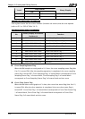
Flag Control
Level
ON
Binary Display
Level 6 Bit 9, Bit 10 Bit 8 0000 0110 0000 0000
Level 7 Bit 8, Bit 9, Bit 10 0000 0111 0000 0000
Screen Number Status Register (SNSR)
This register stores the last screen number (includes sub screen) that the user opened
(refer to D11 or $26 of Table 3-4-2).
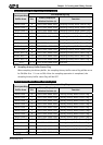
Curve Control Status Register (CCSR)
Bit
Binary Display of Relative
Position (x)
Function
0 0000 0000 0000 000x Curve Sampling Status Flag 1
1 0000 0000 0000 00x0 Curve Sampling Status Flag 2
2 0000 0000 0000 0x00 Curve Sampling Status Flag 3
3 0000 0000 0000 x000 Curve Sampling Status Flag 4
4-7 0000 0000 xxxx 0000 Reserved
8 0000 000x 0000 0000 Curve Clear Status Flag 1
9 0000 00x0 0000 0000 Curve Clear Status Flag 2
10 0000 0x00 0000 0000 Curve Clear Status Flag 3
11 0000 x000 0000 0000 Curve Clear Status Flag 4
12-15 xxxx 0000 0000 0000 Reserved
Curve Sampling Status Flag
When the HMI samples a trend graph or X-Y chart, the curve sampling status flag (bits
0 to 3) is turned ON. After the sampling operation is completed, the curve sampling
status flag is turned OFF. Curve Sampling Flag 1 of control block corresponds to Curve
Sampling Status Flag 1 of status block, Curve Sampling Flag 2 of control block
corresponds to Curve Sampling Status Flag 2 of status block and vise versa.
Curve Clear Status Flag
When the HMI clears trend graph or X-Y chart, the curve clear status flag (bits 8 to 11)
is turned ON. After the clear operation is completed, the curve clear status flag is
turned OFF. Curve Clear Flag 1 of control block corresponds to Curve Clear Status Flag
1 of status block, Curve Clear Flag 2 of control block corresponds to Curve Clear
Status Flag 2 of status block and vise versa.