


Chapter 3 Creating and Editing Screens
Revision May, 2010 3-31
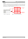
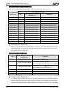
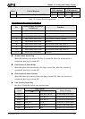
Corresponding Flag
Corresponding
Buffer Area
Bit
Binary Display of Relative
Position (x)
Function
Buffer Area 4 3 0000 0000 0000 x000 Sampling History Buffer 4
Buffer Area 5 4 0000 0000 000x 0000 Sampling History Buffer 5
Buffer Area 6 5 0000 0000 00x0 0000 Sampling History Buffer 6
Buffer Area 7 6 0000 0000 0x00 0000 Sampling History Buffer 7
Buffer Area 8 7 0000 0000 x000 0000 Sampling History Buffer 8
Buffer Area 9 8 0000 000x 0000 0000 Sampling History Buffer 9
Buffer Area 10 9 0000 00x0 0000 0000 Sampling History Buffer 10
Buffer Area 11 10 0000 0x00 0000 0000 Sampling History Buffer 11
Buffer Area 12 11 0000 x000 0000 0000 Sampling History Buffer 12
12-15 xxxx 0000 0000 0000 Reserved
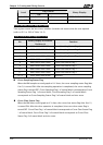
Sampling History Buffer Flag
Bits 0 to 11 control the sampling history buffer operation of HMI by the PLC. When this
flag is turned ON, HMI performs sampling one time. To control the sampling history
buffer flag again, this flag must be turned OFF and then ON again.
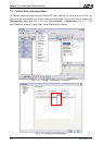
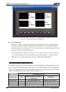
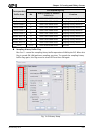
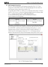
Fig. 3-4-6 History Setup