


D-Link DES-3010FA/GA User Guide
Page 20
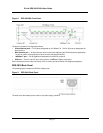
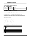
The console LED indications are described in the following table:
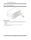
Cable, Port, and Pinout Information
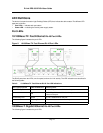
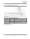
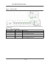
This section describes the devices physical interfaces and provides information about cable connections. Stations
are connected to the device ports through the physical interface ports on the front panel. For each station, the
appropriate mode (Half/Full Duplex, Auto Negotiation) is set. The default is Auto Negotiation.
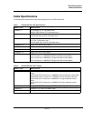
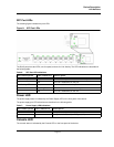
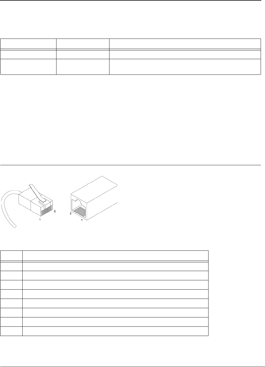
Pin Connections for the 10/100/1000 Ethernet Interface
The switching port can connect to stations wired in standard RJ-45 Ethernet station mode using straight cables.
Transmission devices connected to each other use crossed cables. The following figure illustrates the pin
allocation.
Figure 9: RJ-45 Pin Allocation
The following table describes the pin allocation
Table 8: Console LED Indications
Port Description LED Indication Description
Console Flashing Green Power On Self Test (POST) is in progress.
Green
POST failure. A problem has been discovered during the
POST.
Table 9: RJ-45 Pin Connections for 10/100/1000 Base-TX
Pin Use
1
TxRx 1+
2
TxRx 1-
3
TxRx 2+
4
TxRx 2-
5
TxRx 3+
6
TxRx 3-
7
TxRx 4+
8 TxRx 4-