


Chapter 2 Installation 23
ACTURA Flex 48330 Power System User Manual
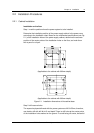
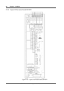
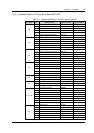
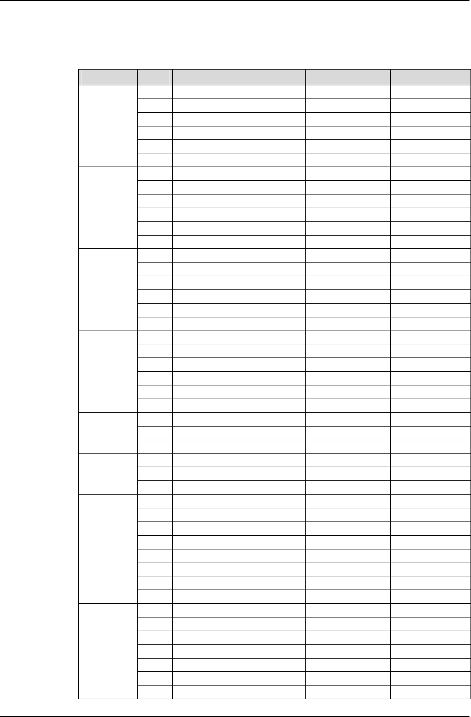
2.3.5 Interface Definition Of Connector Board S6415X2
Table 2-4 Interface definition of connector board S6415X2
Connector Pin Signal name Mark number Logic relation
1 Relay output 1 normal close DO1_NC
2 Relay output 2 normal close DO2_NC
3 Relay output 1 common DO1_COM
4 Relay output 2 common DO2_COM
5 Relay output 1 normal open DO1_NO
J3
6 Relay output 2 normal open DO2_NO
1 Relay output 3 normal close DO3_NC
2 Relay output 4 normal close DO4_NC
3 Relay output 3 common DO3_COM
4 Relay output 4 common DO4_COM
5 Relay output 3 normal open DO3_NO
J4
6 Relay output 4 normal open DO4_NO
1 Relay output 5 normal close DO5_NC
2 Relay output 6 normal close DO6_NC
3 Relay output 5 common DO5_COM
4 Relay output 6 common DO6_COM
5 Relay output 5 normal open DO5_NO
J5
6 Relay output 6 normal open DO6_NO
1 Relay output 7 normal close DO7_NC
2 Relay output 8 normal close DO8_NC
3 Relay output 7 common DO7_COM
4 Relay output 8 common DO8_COM
5 Relay output 7 normal open DO7_NO
J6
6 Relay output 8 normal open DO8_NO
1 Digital circuits power +5V
2 Temperature signal 1 input TEMP1 4~20mA
J10
3 Analog ground GND
1 Digital circuits power +5V
2 Temperature signal 2 input TEMP2 4~20mA
J11
3 Analog ground GND
1 Data Carrier Detect DCD232
2 Receive Data RXD232
3 Transmit Data TXD232
4 Data Terminal Ready DTR232
5 Data Communication ground DGND
6 Empty
7 Request To Send RTS232
J12, J18
8,9 Empty
1 Ethernet TX+ NETTX+
2 Ethernet TX- NETTX-
3 Ethernet TR+ NETTR+
4 Empty
5
Empty
6 Ethernet TR- NETTR-
J13
7~12 Empty