46 Chapter 5 Operating SCU
ACTURA Flex 48330 Power System User Manual
Note
When the DC load 9 and its above (load 10, load 11 …) have circuit fault alarm, the
monitoring module all display “Load 9 Failure” or “Aux Load Fails”.
5.5.4 Changing Audible/Visual Alarm And Alarm Call Back Plan
There are different audible/visual alarms and call back modes for alarms of different
levels. For the products in China market, the alarming mode for major alarms and
critical alarms are the same.
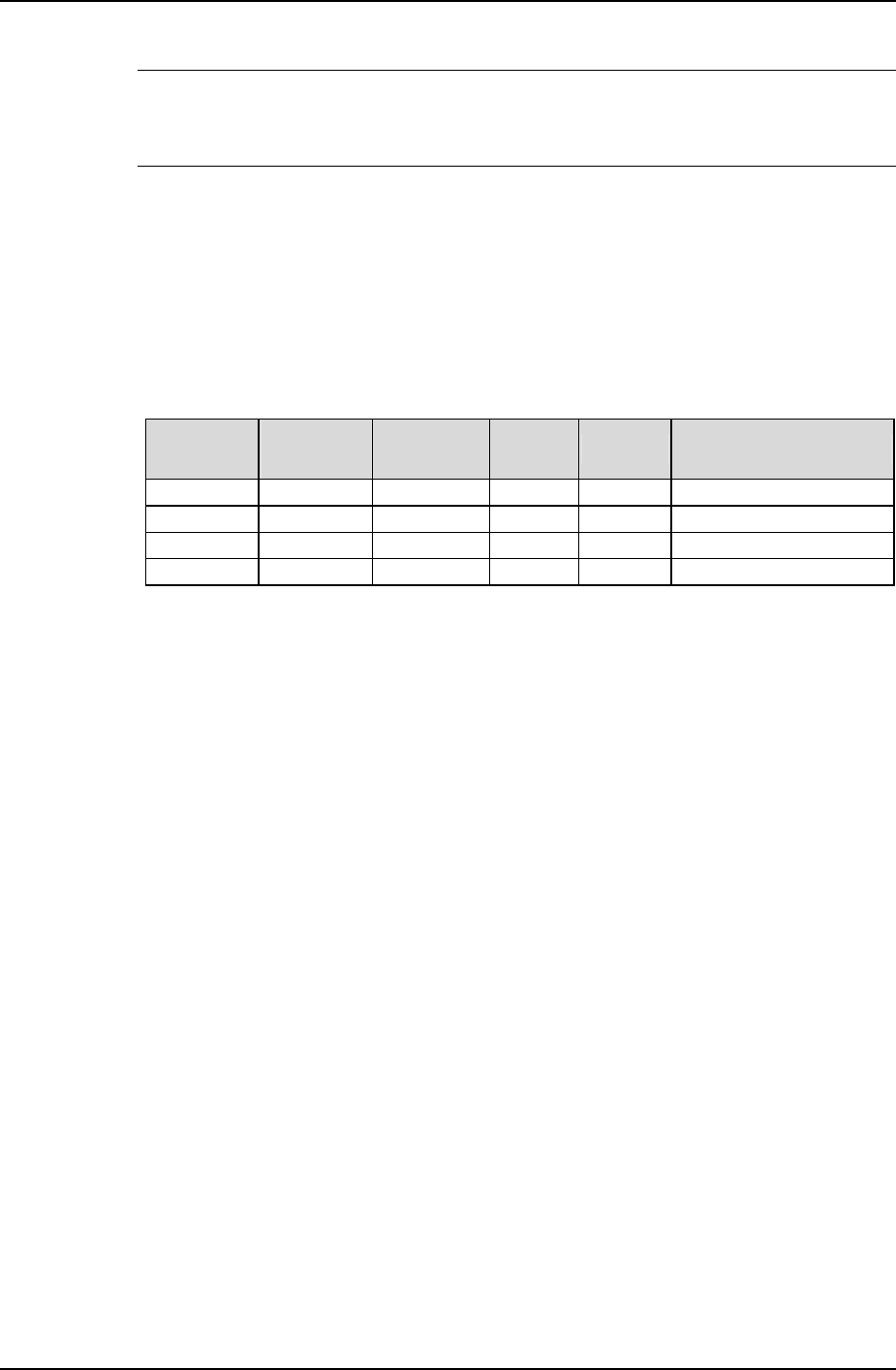
Table 5-4 Changing audible/visual alarm and alarm call back plan
Alarm level
Red
indicator
Yellow
indicator
Alarm
horn
Call back Remark
Critical ON / ON Y Callback No. can be set
Major ON / ON Y Callback No. can be set
Observation / ON OFF N
No alarm OFF OFF OFF N
Therefore, changing the alarm level of different alarms may change their
audible/visual alarm mode and call back plan too.
Pressing any key on the monitoring module can silence the alarm sound. The
sound will disappear and alarm indicator will be off when all alarms are cleared.
You can configure how long an alarm sound will last, or choose to make no alarm
sound. For details, see 5.7.11 Alarms Settings.
5.5.5 Changing Alarm Types Of Dry Contacts
As one of the alarm type parameter, “Related Relay” refers to the serial No. of the
dry contract corresponding to the alarm type, whose value is either 1 ~ 8 or “None”.
“None” means there is no corresponding dry contact. For details, see 4.7.11 Alarms
Settings.
5.5.6 Setting Alarm Type For Dry Contacts
The Programmable Logic Control (PLC) is configured through the host software.
The way to configure the PLC function is:
C = A (Status) * B (Status)
C: The dry contract serial No. of the corresponding output. Range: 1 ~ 8.
A, B: The input alarm type. Status: Whether the alarm has been raised.


