


Chapter 5 Operating SCU 69
ACTURA Flex 48330 Power System User Manual
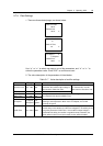
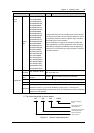
Parameter Range Default Value description
Operator
level or
above
System
Type
24V/75A/500/NONE
24V/75A/500/MAN
24V/75A/500/AUTO
24V/50A/500/NONE
24V/50A/500/MAN
24V/50A/500/AUTO
48V/50A/500/NONE
48V/50A/500/MAN
48V/50A/500/AUTO
48V/50A/300/NONE
48V/50A/300/MAN
48V/50A/300/AUTO
48V/30A/300/NONE
48V/30A/300/MAN
48V/30A/300/AUTO
48V/30A/100/NONE
48V/30A/100/MAN
48V/30A/100/AUTO
48V/15A/100/NONE
48V/15A/100/MAN
48V/15A/100/AUTO
48V/100A/SET/NON
48V/100A/SET/MAN
48V/100A/SET/AUT
48V/50A/SET/NONE
48V/30A/SET/NONE
This parameter has been set according to the actual situation
upon delivery and needs not to be changed. However, when a
new monitoring module is used, its “System Type” should be
set according to the actual situation.
After this parameter is changed, the monitoring module will
restart automatically, and other parameters of the monitoring
module will be changed to the defaults of the corresponding
system type. You should change some parameters according
to the actual situation.
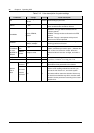
Change
Password
User, Operator, Admin
The password can be 6 digits long at most. If it is shorte than 6
digits, end it with a “#”
Con Alarm
Voice
3min, 10min, 1h, 4h,
constant
Contstant The period that an alarm sound will last
Serial The production serial No. of the monitoring module. This parameter cannot be changed
SW Ver The software version No. of the monitoring module. This parameter cannot be changed
Administrator
Set Enable
Reflecting the jumper status of a hardware switch within the monitoring module. If this
parameter is set to ”N”, you are not allowed to use the jumper, nor change any
parameter except the battery management mode. The maintenance over the monitoring
module will not be affected
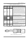
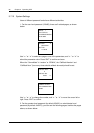
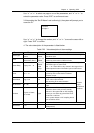
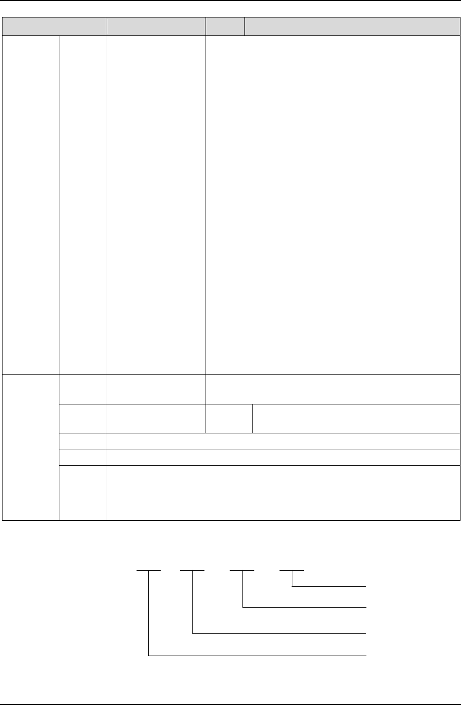
5. The model description is shown below:
48V / 30A / 300 / NONE
No AC data acquisition
board
System shunt coefficient:
100/300/500/SET
Rectifier rated output current:
15A/30A/50A/75A/100A
Rectifier rated output
voltage: 48V/24V
Figure 5-4 System model description