


48 Chapter 5 Operating SCU
ACTURA Flex 48330 Power System User Manual
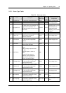
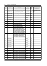
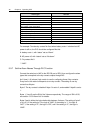
Alarm type Remark
BLVD
Output voltage abnormal
AC power off
Multiple rectifiers alarm
Time for system maintenance (replace the fan)
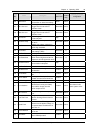
Any rectifier comm interrupted
Any rectifier AC power off
Any rectifier over-temperature
Any rctifier faulty
Any rectifier in protection
Any rectifier fan faulty
Any AC derated rectifier
Any temperature derated rectifier
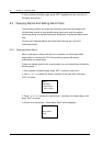
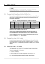
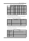
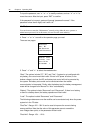
For example: To make dry contact No.3 act when battery route 1 is broken but AC
power is still on, the PLC should be configured like this:
A: battery route 1, with “status” set as “Alarm”.
B: AC power off, with “status” set as “No alarm”.
C: Dry contact No.3
*: “AND”.
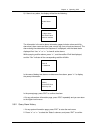
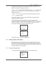
5.5.7 Set the Alarm Names Through PLC Function
Connect the serial port of MC to the RS-232 port of SCU, then configure the alarm
types that correspond to the dry contact outputs through MC.
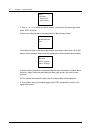
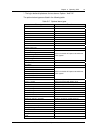
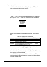
An 8 (row) % 6 (column) logic matrix is used in configuring these 8 dry contacts.
Every row in the matrix corresponds to one dry contact. The setting of one dry
contact has 6 bytes.
Byte 0: The dry contact is disabled if byte 0 is set to 0, and enabled if byte0 is set to
1.
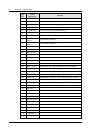
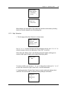
Bytes 1, 3 and 5 are the SN of the 3 alarms respectively. The range of SN is 0-56,
see section “5.5.3 Alarm List” for details.
Bytes 2 and 4 define the logic relationship between 3 alarms. The setting of byte 2
or 4 is 0-3. If the setting is 0, the logic is “AND”; If the setting is “1”, the logic is
“NOT”; If the setting is “2”, the logic is “OR”; and if the setting is “3”, the logic is
“AND”.