


Chapter 5 Operating SCU 59
ACTURA Flex 48330 Power System User Manual
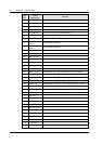
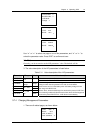
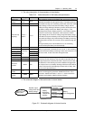
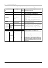
Table 5-12 Charging management parameter value description
Parameter Range Default Value description
Float 53.5V
In the FC state, all rectifiers output
voltage according to the set “Float”
Boost
42V ~ 58V
56.4V
In the BC state, all rectifiers output
voltage according to the set “Boost”
The “Boost” must be
higher than the “Float”
Limit (current
limit)
0.1 ~ 0.25C
10
0.1C
10
When the monitoring module detects that the battery charging
current is higher than the “Limit”, it will control the current of the
rectifiers, through which it can limit the battery charging current.
C
10
is the battery rated capacity, generally set to 10 ~ 20% of the
rated capacity of one battery string.
Over (over current
point)
0.3C
10
~ 1.0C
10
0.300C
10
When the monitoring module detects that the battery charging
current is higher than the “Over”, it will raise the battery charge
over-current alarm.
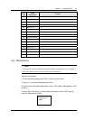
Automatic Boost Select “Y”, and BC will be conducted when conditions allow
Cyclic Boost
Yes, No Y
Cyclic Boost
Interval
48 ~ 8760h 2400h
Cyclic Boost Time 30 ~ 2880min 720min
Select “Y”, and the monitoring module will control the system to
enter the Cyclic Boost when the FC time reaches the “Cyclic Boost
Interval”. The battery charging voltage is the preset “Boost”, and
the time is the preset “Cyclic Boost Time”
To Boost Current 0.50 ~ 0.80C
10
0.06C
10
To Boost
Capacity
0.1 ~ 0.95 0.80
The monitoring module will control the system enter the BC state
when the battery capacity decreases to the value of “To Boost
Capacity”, or when the charge current reaches the “To Boost
Current”. The charge voltage will be the “Boost”.
Constant BC Curr 0.02 ~ 0.99C10 0.01C
10
Duration (of
constant BC)
30 ~ 1440min 180min
The system in the BC state will enter the FC state when the charge
current decreases to the “Constant BC Curr” and after the
“Duration”. The battery charge voltage then will be the “Float”.
Boost Limit 60 ~ 2880min 1080min
To ensure safety, the monitoring module will forcefully control the
system to enter the FC state if during the BC state, the BC time
reaches the “Boost Limit”, or abnormalities occur (such as AC
failure and battery route faulty, etc.).
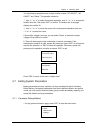
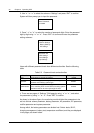
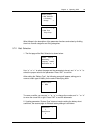
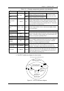
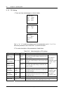
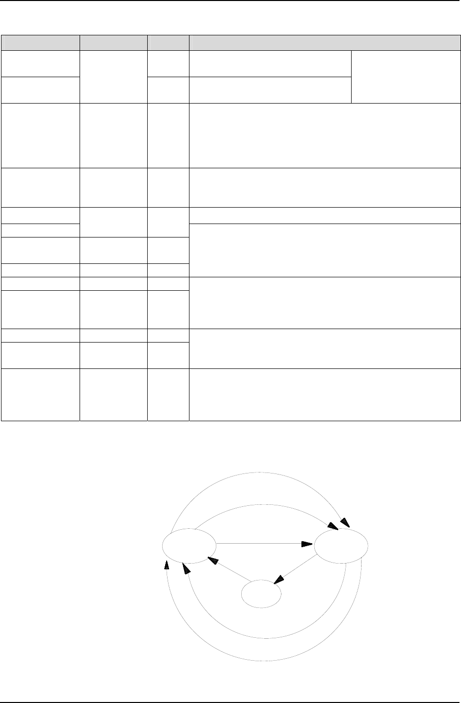
3. The BC/FC switchover diagram is shown below:
Battery charge current
bigger than "To BC Current"
Battery capacity smaller
than "To BC Capacity"
Abnormal situation
FC
BC
Constant BC
time-up
Charge current
smaller than
"Constant BC
Curr"
Constant
BC
BC time longer than
"BC LVD Time"
FC time longer than "Scheduled BC Interval"
Figure 5-2 BC/FC switchover diagram