


Table List
Table 1-1 Configurations of Actura Flex 48330 Power System..............................................3
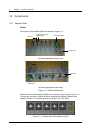
Table 1-2 Dimensions of rectifier shelf...................................................................................5
Table
1-3 Function of indicators.............................................................................................7
Table 1-4 Authority and default password..............................................................................9
Table 1-5 Configuration of MFU...........................................................................................10
Table 1-6 BCU configuration................................................................................................11
Table
2-1 Environmental conditions in power room .............................................................12
Table 2-2 AC input modes ...................................................................................................17
Table 2-3 Configuration number of load MCBs and battery MCBs.......................................20
Table 2-4 Interface definition of connector board S6415X2 .................................................23
Table
3-1 System checklist before startup ...........................................................................30
Table 5-1 Functions of LED indicators .................................................................................34
Table 5-2 Functions of SCU keys.........................................................................................34
Table 5-3 Alarm type table
...................................................................................................43
Table 5-4 Changing audible/visual alarm and alarm call back plan......................................46
Table 5-5 Optional alarm types ............................................................................................47
Table 5-6 Logic matrix used for configuring 8 dry contacts..................................................49
Table 5-7 Example of PLC setting........................................................................................49
Table 5-8 PLC SN and Alarm...............................................................................................49
Table
5-9 Password levels and authorities...........................................................................54
Table 5-10
Value description of the basic battery parameters .............................................56
Table 5-11 Value description of the LVD parameters...........................................................57
Table
5-12 Charging management parameter value description..........................................59
Table 5-13 Value description of the battery test parameters................................................61
Table 5-14 Value description of temperature compensation coefficient...............................62
Table 5-15 Value description of AC se
ttings ........................................................................63
Table 5-16 Value description of DC se
ttings........................................................................64
Table 5-17 Value description of rectifier settings..................................................................65
Table 5-18 Value description of system settings
..................................................................68
Table 5-19 Relationship between system model and system type.......................................70
Table 5-20 Value description of alarm settings ....................................................................71
Table 7-1 Troubleshooting ...................................................................................................75