


Chapter 5 Operating SCU 61
ACTURA Flex 48330 Power System User Manual
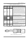
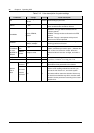
2. The value description of the parameters is listed below:
Table 5-13 Value description of the battery test parameters
Parameter Range Default Value description
Battery test
voltage
43.1V ~
57.9V
45.2V
Battery test time 5 ~ 1440min 300min
Test End Cap
(capacity)
0.01C
10
~
0
.95C
10
0.7C
10
The monitoring module can do battery test, and record 10 sets of
test data (accessible only through the host). The battery test has to
be started manually, then monitoring module will control the rectifier
output voltage, make it lower than the battery voltage, and the
battery discharge will begin. Monitoring module will stop the test if
the battery voltage reaches the “Battery test voltage”, or the
discharge time reaches “Battery test time”, or the battery capacity
reaches “Test End Cap”. Afterwards, it will restore the rectifier
output voltage to the normal FC voltage, begin the battery charge
and switch the system to battery auto-management. Meanwhile the
test start time/voltage and end time/voltage and battery remaining
capacity will be recorded. The records can be queried through the
host.
During the battery test, if abnormalities occur, the monitoring
module will stop the battery test automatically.
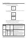
Scheduled Test Y, N Y
Planned Test 1 00:00, Jan. 1
st
Planned Test 2 00:00, April 1
st
Planned Test 3 00:00, July 1
st
Planned Test 4
Month,day,
hour
00:00, Oct. 1
st
When the parameter “Scheduled Test” is set to “Y”, the monitoring
module will test the battery according to the 4 sets of test time. You
can set at most 12 sets of test time through the host.
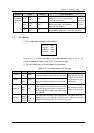
Alarm Current 1A ~ 100A 10A
ShortTest Cycle 24h ~ 8,760h 720h
ShortTest
Duration
1 ~ 60min 5min
If the battery have not discharged within the “ShortTest Cycle”, the
monitoring module will start a short test, whose operation time is
set by the parameter “ShortTest Duration”. By the end of the test, if
the difference in the discharge currents of batteries is bigger than
the “Alarm Current”, the battery discharge imbalance alarm will be
raised. This alarm will automatically end after 5min of delay. Also
you can end it by confirming it.
StableTest
Enable
Y, N
StableTest
Current
0 ~ 9999A 9999A
The stable test is conducted with constant battery current, whose
value is set through the parameter “StableTest Current”. If the
parameter “StableTest Enable” is set to “Y”, and the test will be
started once the battery satisfies the test condition
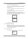
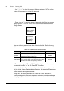
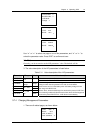
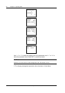
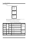
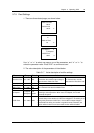
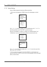
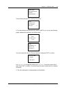
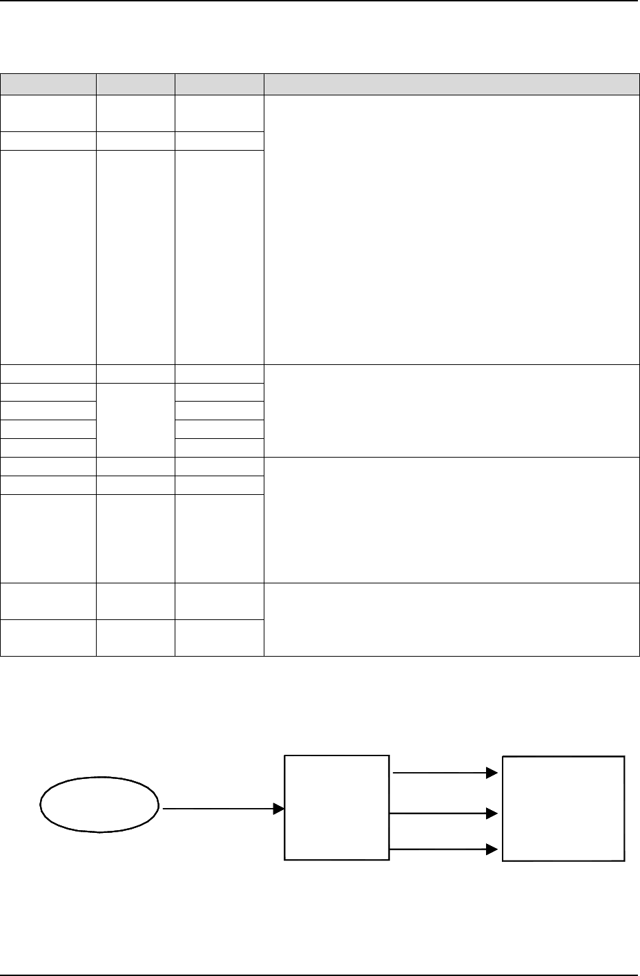
3. The schematic diagram of the test function is shown below:
Battery
Auto-management
Manually start
battery test
Rectifier output
voltage lower than
battery voltage
Battery
discharges
Rectifier hot
standby
"Test End Voltage"
is reached
"Test End Cap" is
reached
"Test End Time" is
reached
Figure 5-3 Schematic diagram of the test function