UM1M820BNA User Instructions
Issue AH, March 4, 2013 Spec No. 1M820BNA (Model M820B)
Spec No. 1M820DNA (Model M820D)
96 Chapter 3. Local Display Menus
This document is property of Emerson Network Power, Energy Systems, North America, Inc. and contains confidential and proprietary information owned by Emerson Network Power, Energy
Systems, North America, Inc. Any copying, use, or disclosure of it without the written permission of Emerson Network Power, Energy Systems, North America, Inc. is strictly prohibited.
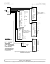
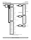
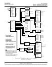
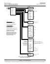
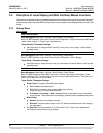
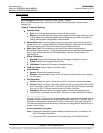
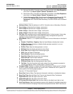
"All Rect Set" Parameter Settings:
HVSD: Enables or disables the High Voltage Shutdown feature for all rectifiers.
HVSD Limit: Sets the High Voltage Shutdown point for all rectifiers.
Restart on HVSD: Enables or disables the High Voltage Shutdown Restart feature for all
rectifiers.
HVSD Restart T: When the High Voltage Shutdown Restart feature is enabled and the
output exceeds the high voltage limit, the rectifiers restart after this time period expires.
Start Interval: Sets the sequence start interval (time period between starting each rectifier
in the system).
Walk-In: Enables or disables the start-up walk-in feature for all rectifiers.
Walk-In Time: Sets the walk-in time period for all rectifiers.
Turn On ACOverV: Enables or disables the "Turn On AC Over Voltage" feature. When the
system is operating on “week” grid input power (i.e. diesel generator), the input voltage
may have a very high peak voltage which may cause a rectifier not to turn on. If “Turn On
AC Over Voltage" feature is enabled, the rectifier is forced to turn on.
ECO Mode: Enables or disables the Energy Optimization feature for all rectifiers. When
enabled, the following parameters can be set.
Best Oper Point: Percent of full load capacity that the rectifiers operate under in the
Energy Optimization mode.
Fluct Range: If load fluctuation is less than this value, rectifiers are not turned on or off
for Energy Optimization.
Energy Save Pt: Energy Optimization is disabled if the load is greater than this setting.
Cycle Period: This is the time period that rectifiers are turned on and off to maintain an
equal operating time for all rectifiers in the system.
Rects ON Time: Time all rectifiers are turned on at End of Cycle.
Turn Off Delay: When the Energy Optimization feature determines a rectifier can be
switched off, this is the time delay before the rectifier is switched off.
Input Curr Lmt: Sets the Input Current Limit point for all rectifiers.
MixHE Power: Allows the system to use rectifiers of different output capacity. When set to
derated power, the output capacity of the higher capacity rectifiers are set to the capacity of
the lowest.
DG Pwr Lmt: Enables or disables the Diesel Power Limit feature. This feature limits
rectifier output power to a percentage of maximum when AC input is supplied by a
diesel-alternator set.
Diesel DI Input: Designates which digital input controls operation of the Diesel Power
Limit feature.
DG Pwr Lmt Pt: Sets, as a percentage, the maximum output power at which rectifiers
can operate when: 1. the Diesel Power Limit feature is enabled and 2. a digital input
signal is received from the connected diesel-alternator set.
Current Limit: Enables or disables output current limit.
Current Limit Pt: Sets the output current limit point.
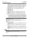
Rect #1 Menu
Menu Navigation: Main Menu / Settings / Rectifier / Rect #1
Note: For WEB Interface; menu items are found under Device Information / Rectifier Group /
Rectifier #1 / Settings Tab.


