


User Instructions UM1M820BNA
Spec No. 1M820BNA (Model M820B) Issue AH, March 4, 2013
Spec No. 1M820DNA (Model M820D)
Chapter 2. Operation 39
This document is property of Emerson Network Power, Energy Systems, North America, Inc. and contains confidential and proprietary information owned by Emerson Network Power, Energy
Systems, North America, Inc. Any copying, use, or disclosure of it without the written permission of Emerson Network Power, Energy Systems, North America, Inc. is strictly prohibited.
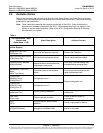
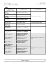
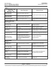
Table 4
Full Alarm Name - WEB
(Abbreviated
Alarm Name - LCD)
Alarm Description
Action to Correct
DI1Alarm
(DI1 Alarm)
Digital input #1 alarm is active.
Check why alarm is active.
…
…
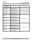
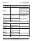
DI7Alarm
(DI7 Alarm)
Digital input #7 alarm is active.
DI8 ESTOP
(DI8 ESTOP)
Digital input #8 alarm is active.
IB Communication Fail
(IB Comm Fail)
ACU+ Interface Board
communications failure.
Check communications cables.
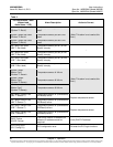
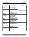
Relay Testing
(Relay Testing)
Relay Test in progress.
--
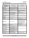
Testing Relay 1
(Testing Relay 1)
Testing Relay 1 (on IB2 Board).
--
…
…
Testing Relay 8
(Testing Relay 8)
Testing Relay 8 (on IB2 Board).
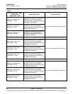
System Temp1 High 2
(System T1 Hi2)
Temperature sensor #1 sensing
temperature higher than high
temperature threshold 2.
Note: This alarm is not used at this
time.)
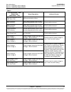
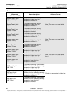
System Temp1 High 1
(System T1 Hi1)
Temperature sensor #1 sensing
temperature higher than high
temperature threshold 1.
System Temp1 Low
(System T1 Low)
Temperature sensor #1 sensing
temperature lower than low
temperature threshold.
System Temp2 High 2
(System T2 Hi2)
Temperature sensor #2 sensing
temperature higher than high
temperature threshold 2.
Note: This alarm is not used at this
time.)
System Temp2 High 1
(System T2 Hi1)
Temperature sensor #2 sensing
temperature higher than high
temperature threshold 1.
System Temp2 Low
(System T2 Low)
Temperature sensor #2 sensing
temperature lower than low
temperature threshold.