


UM1M820BNA User Instructions
Issue AH, March 4, 2013 Spec No. 1M820BNA (Model M820B)
Spec No. 1M820DNA (Model M820D)
32 Chapter 2. Operation
This document is property of Emerson Network Power, Energy Systems, North America, Inc. and contains confidential and proprietary information owned by Emerson Network Power, Energy
Systems, North America, Inc. Any copying, use, or disclosure of it without the written permission of Emerson Network Power, Energy Systems, North America, Inc. is strictly prohibited.
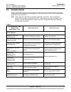
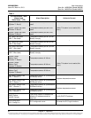
Parameters
Current1 Break Value (A) (Device rating.)
Current1 High Current Limit (% of Current# Break Value.)
Current1 Very High Current Limit (% of Current# Break Value.)
Shunt # Current (Rating of Shunt.)
Shunt # Voltage (Rating of Shunt.)
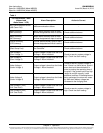
2.5.38 Setting the Load Current Alarm
Local Menu Navigation: Main Menu / Settings / Power System / General / Load Curr Alarm.
WEB Menu Navigation: Device Information / Power System / Settings Tab / Load Current Alarm.
Enter a value (in AMPS). If load current exceeds this value, a load current alarm is issued.
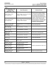
2.5.39 Placing the System in Float or Equalize Charge Mode
Local Menu Navigation: Main Menu / Manual / Batt Group / “EQ/FLT Control”.
WEB Menu Navigation: Device Information / Battery Group / Control Tab / “Equalize/Float” Charge
Control.
2.5.40 Manually Forcing Relays
See also “2.5.42 Using the Relay Test Feature”.
Place Controller in Manual Mode, then...
Local Menu Navigation: Main Menu / Manual / Power System / Relay Output [number].
Main Menu / Manual / EIB / EIB1 / Relay Output [number].
Select the other state for an alarm relay (active / not active).
After confirming the change, the alarm relay will momentarily toggle to the chosen state. The alarm
relay then reverts back to being controlled by the ACU+.
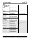
WEB Menu Navigation: Device Information / Power System / Control Tab.
Device Information / EIB Group / EIB1 / Control Tab.
The Control Tab allows you to change the state of an alarm relay.
In the "Set value" box, select the other state for an alarm relay (active / not active).
Click on "set".
After confirming the change, the alarm relay will momentarily toggle to the chosen state. The alarm
relay then reverts back to being controlled by the ACU+.
2.5.41 Manually Forcing LVDs
Place Controller in Manual Mode, then...
Local Menu Navigation: Main Menu / Manual / LVD / LVD Unit.
Select the other state for an LVD (connected/disconnected).
After confirming the change, the LVD will momentarily toggle to the chosen state. The LVD then
reverts back to being controlled by the ACU+.
WEB Menu Navigation: Device Information / LVD Group / LVD Unit / select the Control Tab.
The Control Tab allows you to change the state of an LVD.
In the "Set value" box, select the other state for an LVD (connected/disconnected).
Click on "set".