User Instructions UM1M820BNA
Spec No. 1M820BNA (Model M820B) Issue AH, March 4, 2013
Spec No. 1M820DNA (Model M820D)
Chapter 6. Replacement Procedures 165
This document is property of Emerson Network Power, Energy Systems, North America, Inc. and contains confidential and proprietary information owned by Emerson Network Power, Energy
Systems, North America, Inc. Any copying, use, or disclosure of it without the written permission of Emerson Network Power, Energy Systems, North America, Inc. is strictly prohibited.
3) Connect an approved grounding strap to your wrist. Attach the other end to a suitable ground.
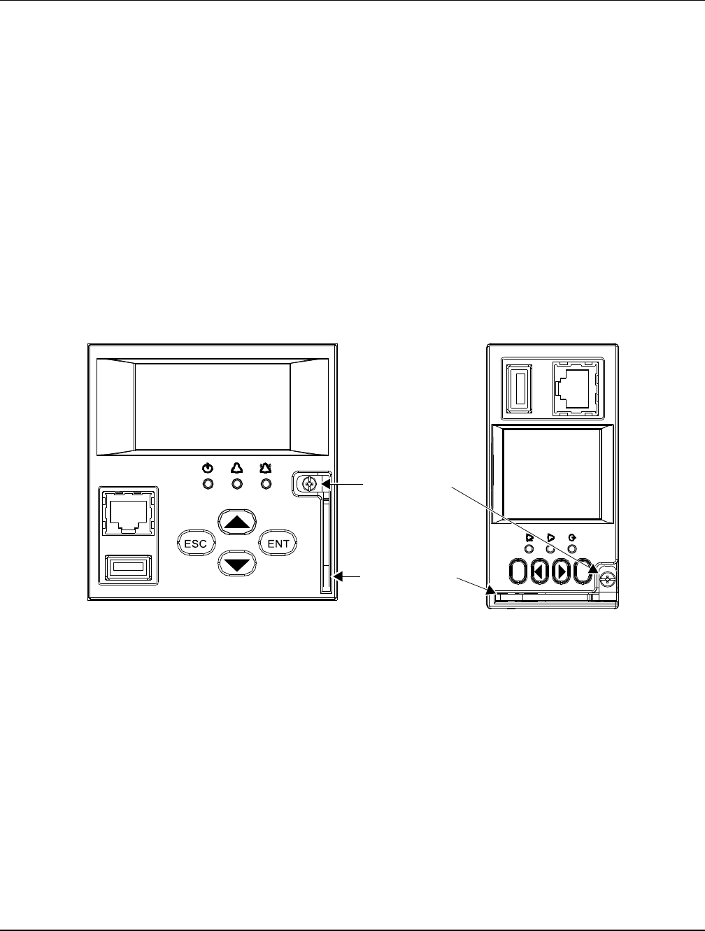
4) Loosen the captive fastener securing the latch mechanism to the front of the ACU+ Controller. Pull
the latch mechanism away from the ACU+ Controller (this will retract the latch mechanism located
on the bottom of the ACU+ Controller). This unlocks the ACU+ Controller from the shelf. Refer to
Figure 10.
5) Slide the ACU+ Controller completely from the shelf.
6) Loosen the captive fastener securing the latch mechanism to the front of the replacement ACU+
Controller. Pull the latch mechanism away from the ACU+ Controller (this will retract the latch
mechanism located on the bottom of the ACU+ Controller).
7) Slide the ACU+ Controller completely into its mounting position.
8) Push the latch mechanism into the front panel of the ACU+ Controller, and secure by tightening the
captive fastener. This locks the ACU+ Controller securely to the shelf.
9) Wait for the Controller to finish booting and verify that the complete system operates normally.
10) Enable the external alarms, or notify appropriate personnel that this procedure is finished.
11) Ensure that there are no local or remote alarms active on the system.
Figure 10
Latch Mechanism on the ACU+ Controller
Captive Fastener
Latch Mechanism
ESC
ENT
M820D M820B


