


UM1M820BNA User Instructions
Issue AH, March 4, 2013 Spec No. 1M820BNA (Model M820B)
Spec No. 1M820DNA (Model M820D)
76 Chapter 2. Operation
This document is property of Emerson Network Power, Energy Systems, North America, Inc. and contains confidential and proprietary information owned by Emerson Network Power, Energy
Systems, North America, Inc. Any copying, use, or disclosure of it without the written permission of Emerson Network Power, Energy Systems, North America, Inc. is strictly prohibited.
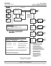
Note 2: If the parallel power system incorporates a main plant shunt, the connections of the cables
from the ACU+ power system to the parallel power system shall be made on the main charge
busbars (rectifier side of the shunt).
Note 3: To compensate for voltage drop, it is recommended to connect the ACU+ power system’s
remote sense leads (if available) to the same point of sensing as the parallel power system.
Note 4: There shall be only one battery return reference (BRR) cable for the two power systems. If
the cable is appropriately sized on the parallel power system, keep it as the BRR for both
power systems. If the cable is not appropriately sized on the parallel power system, install a
new BRR cable and connect it preferably to the ACU+ power system since the parallel power
system may eventually be phased out.
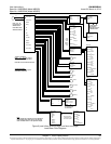
Note 5: If battery disconnect units (BDUs) are used on the new or parallel power system, these shall
be wired in such a way as to be all triggered simultaneously in order to prevent any
overloading of these.
Note 6: For the size and number of bridge cables between the two power systems, take into
consideration the voltage drop, the available connecting points in each system, as well as
the fact that these cables are unfused and shall therefore be run on a dedicated cable rack.
“C” or “H” taps may be used to make full use of available connecting points.
Note 7: The legacy system retains the function of its controller and the percent of load on each plant
is controlled by the ACU+. Alarms may be sent individually from each plant, or combined
using an ACU+ Interface Board and the programmable relays resident in the controller.
Note 8: Add a label on both power systems to indicate that these are operating in the Power Split
Mode with each other.
Optional Function Connections: The following signals from the existing system must be connected
to digital inputs of the ACU+ system interface board for these functions to be active: Equalize Charge
in Progress, Battery Test in Progress, Load LVD Active, and Battery LVD Active. Otherwise disable
these functions.