


User Instructions UM1M820BNA
Spec No. 1M820BNA (Model M820B) Issue AH, March 4, 2013
Spec No. 1M820DNA (Model M820D)
Chapter 1. Introduction 3
This document is property of Emerson Network Power, Energy Systems, North America, Inc. and contains confidential and proprietary information owned by Emerson Network Power, Energy
Systems, North America, Inc. Any copying, use, or disclosure of it without the written permission of Emerson Network Power, Energy Systems, North America, Inc. is strictly prohibited.
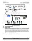
1.3.3 System Components Monitoring and System Alarms Generation
The ACU+ Controller monitors the components comprising the system (such as the rectifiers, converters,
and supervisory modules) and generates alarms if a fault condition occurs. The ACU+ Controller also
maintains an alarm history log.
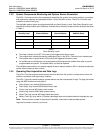
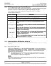
The available system alarms are programmed with an Alarm Severity Level. Each Alarm Severity Level
has different visual/audible alarm attributes. Available Alarm Severity Levels and their attributes are listed
in Table 1.
Alarm
Severity Level
ACU+ Red
Alarm Indicator
ACU+ Yellow
Alarm Indicator
ACU+
Audible Alarm
Critical Alarm (CA)
ON
OFF
ON
Major Alarm (MJ)
ON
OFF
ON
Minor Alarm (MN)
OFF
ON
OFF
No Alarm
OFF
OFF
OFF
Table 1
Alarm Severity Levels
The alarm indicator turns OFF if the fault(s) that triggered the alarm clears.
The audible alarm can be silenced by pressing any key on the ACU+ Controller local interface pad.
The audible alarm is also silenced if the fault(s) that triggered the alarm clears.
An audible alarm cutoff feature can be programmed that silences the audible alarm after a pre-set
programmable time period. The audible alarm can also be disabled.
The available system alarms can also be mapped to alarm relays (located on ACU+ interface boards) that
can be wired to external alarm circuits.
1.3.4 Operating Data Acquisition and Data Logs
The ACU+ Controller acquires and analyses real time data from the system’s components such as the
rectifiers, converters, and supervisory modules.
The ACU+ Controller uses this data to process alarms and also records data in logs. The logs are viewed
using the WEB Interface and consists of...
Alarm History Log: records 600 latest alarms.
Data History Log: records 60000 latest history data.
Control Log: records 500 latest control events.
System Log: records 3000 latest system events.
Diesel Test Log: records 500 latest diesel test results.
Battery Test Log: up to twelve (12) battery discharge tests can be performed and recorded per year.
Note: Once maximum number of log entries is reached, new entries overwrite oldest entries.
Logs can be saved in the text (.txt) format.