


S1F76300 Series
S1F70000 Series EPSON 4–13
Technical Manual
S1F76300
Series
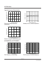
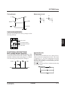
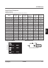
Timing diagram Measurement circuit
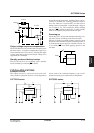
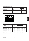
PACKAGE MARKINGS
S1F76310, S1F76380 series device packages use the
following markings.
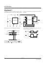
FUNCTIONAL DESCRIPTIONS
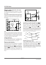
Basic Voltage Booster Operation
Tr1 switches ON and OFF at half the frequency of the
clock pulses from the built-in RC oscillator. When the
transistor is ON, the circuit stores energy in L. When it
is off, this energy flows through D to change C.
Internal Circuits
CR oscillator
The S1F76310, S1F76380 series use a built-in CR os-
cillator to drive the voltage booster circuit. The circuit
is supplied by V
I1. All circuit components are on-chip
and thus the drive frequency is set internally. To ensure
50% duty, this frequency is twice that used by the volt-
age booster circuit.
When PS is Low, the oscillator is disabled and the chip
is in standby mode.
V
I1
t
pd
PWCR
RST
7631
Series number
Second subcode character
Code number
First subcode character
V
O
R 100 kΩ
PWCR RST
C
V
O
V
I1
GND
V
O
GND
LD
Tr1 C
PS
C
R