


S1F76610 Series
2–14 EPSON S1F70000 Series
Technical Manual
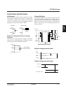
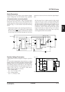
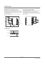
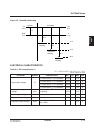
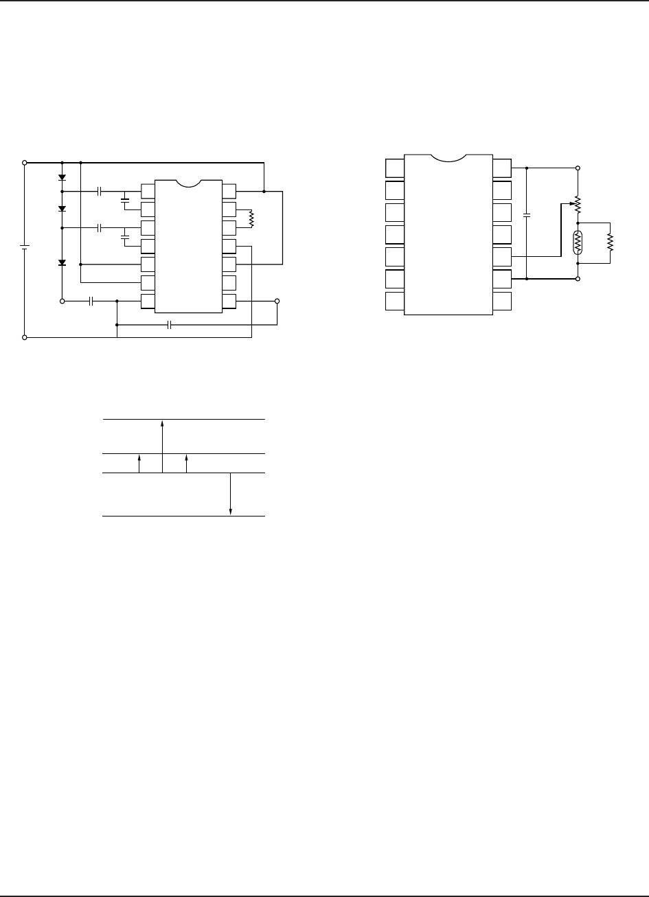
Simultaneous Voltage Conversion
Combining a standard voltage tripler circuit with one
for positive voltage conversion generates both –15 and
8.2V outputs from a single input, however, it also raises
the output impedance.
A voltage doubler generates –10 and 3.8V outputs.
Potential levels
VDD = 0 V
V
I = –5 V
V
O1 = –15 V
V
O2 = 8.2V
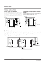
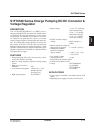
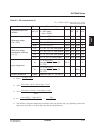
Using an External Gradient
The S1F7661C0B0/M0B0 offers three built-in tem-
perature gradients— –0.1, –0.4 and –0.6%/°C.
To set the gradient externally, place a thermistor, R
T, in
series with the variable resistor, R
RV, used to adjust the
output voltage.
R
T
V
REG
R
RV
R1
10 µF
V
DD
R
P
+
1
2
3
4
5
6
7
14
13
12
11
10
9
8
V
DD
= 0 V
V
I
= –5 V
V
O2
= 8.2 V
V
O1
= –15 V
+
+
10 µF
10 µF
10 µF
10 µF
10 µF
10 µF
+
R
OSC
1 MΩ
D1
D2
5 V
D3
+
++
1
2
3
4
5
6
7
14
13
12
11
10
9
8