S1F76300 Series
S1F70000 Series EPSON 4–29
Technical Manual
S1F76300
Series
Diode
Use a Schottky barrier diode with a high switching
speed and low forward voltage drop, V
F.
Capacitor
To minimize ripple voltages, use capacitors with a
small equivalent direct-current resistance for smooth-
ing.
Sample External Components
Leadless inductors
TDK NLF453232 series magnetically-shielded leadless inductors
Inductance LQ frequency
Device
DC resistance Rated current
Device
(
µ
H)
Qmin
(MHz)
freuquency
(
Ω
-Max.) (mA-Max.)
(MHz-Min.)
NLF453232-390K 39.0 ±10% 50 2.52 13 1.89 44
NLF453232-470K 47.0 ±10% 50 2.52 12 2.10 41
NLF453232-560K 56.0 ±10% 50 2.52 11 2.34 39
NLF453232-680K 68.0 ±10% 50 2.52 10 2.60 36
NLF453232-820K 82.0 ±10% 50 2.52 10 2.86 34
NLF453232-101K 100.0 ±10% 50 0.796 9 3.25 32
NLF453232-121K 120.0 ±10% 50 0.796 8 3.64 30
NLF453232-151K 150.0 ±10% 50 0.796 7 4.16 28
NLF453232-181K 180.0 ±10% 40 0.796 6 5.72 26
NLF453232-221K 220.0 ±10% 40 0.796 5.5 6.30 24
NLF453232-271K 270.0 ±10% 40 0.796 5 6.90 23
NLF453232-331K 330.0 ±10% 40 0.796 4.5 7.54 23
NLF453232-391K 390.0 ±10% 40 0.796 4 8.20 21
NLF453232-471K 470.0 ±10% 40 0.796 3.8 9.20 19
NLF453232-561K 560.0 ±10% 40 0.796 3.6 10.50 18
NLF453232-681K 680.0 ±10% 40 0.796 3.4 12.00 17
NLF453232-821K 820.0 ±10% 40 0.796 3 13.50 16
NLF453232-102K 1000.0 ±10% 40 0.252 2.5 16.00 15
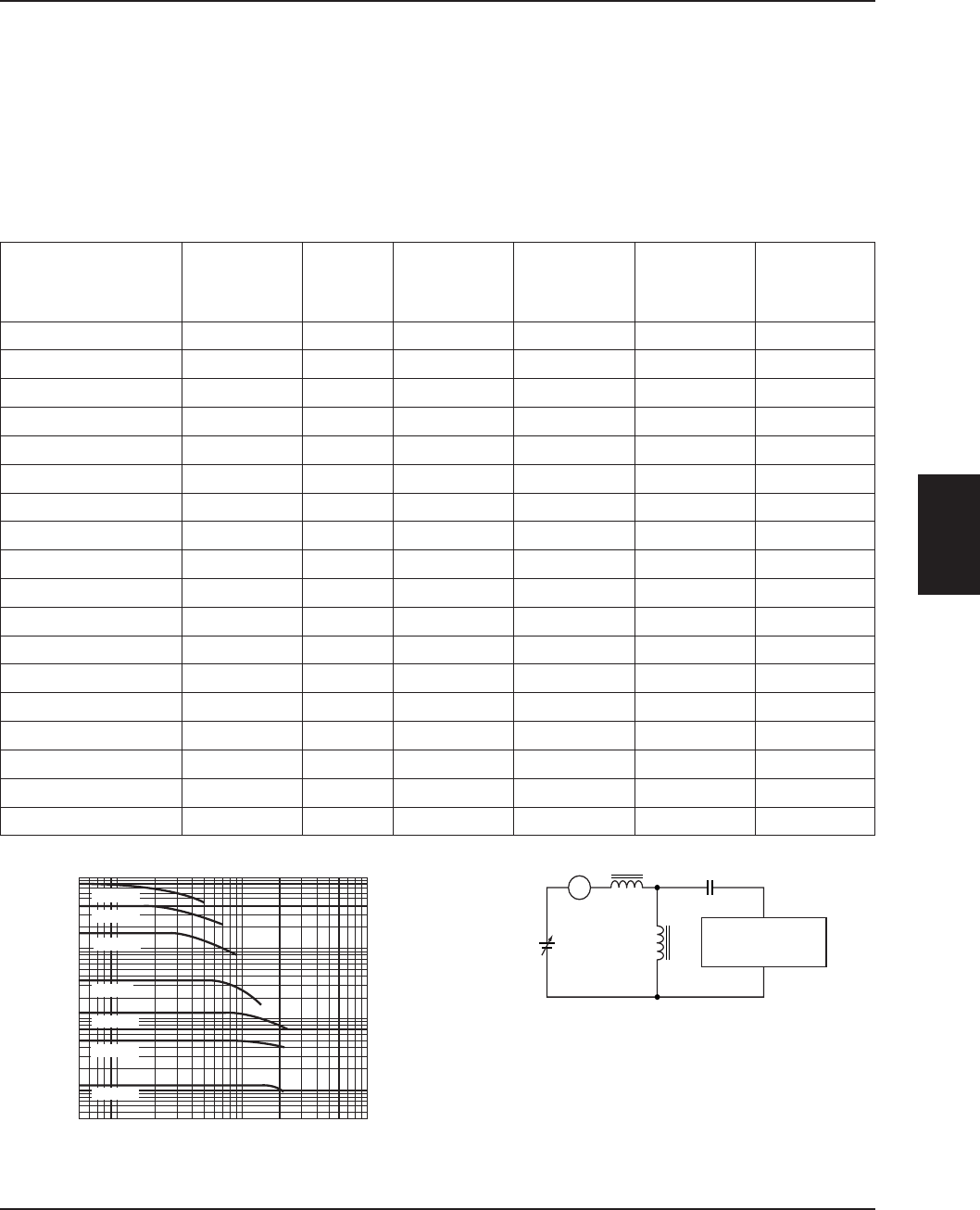
Characteristic response Measurement circuit
1000
10
Inductance (µH)
100
DC current (mA)
100050050
500
100
50
10
5
1
33 µH
10 µH
4.7 µH
1.0 µH
150 µH
390 µH
820 µH
DC
supply
5H
20,000 µF
Lx
A
YHP4255A
universal bridge


