


S1F76300 Series
4–32 EPSON S1F70000 Series
Technical Manual
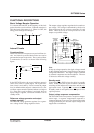
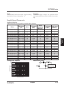
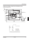
Other Applications
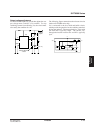
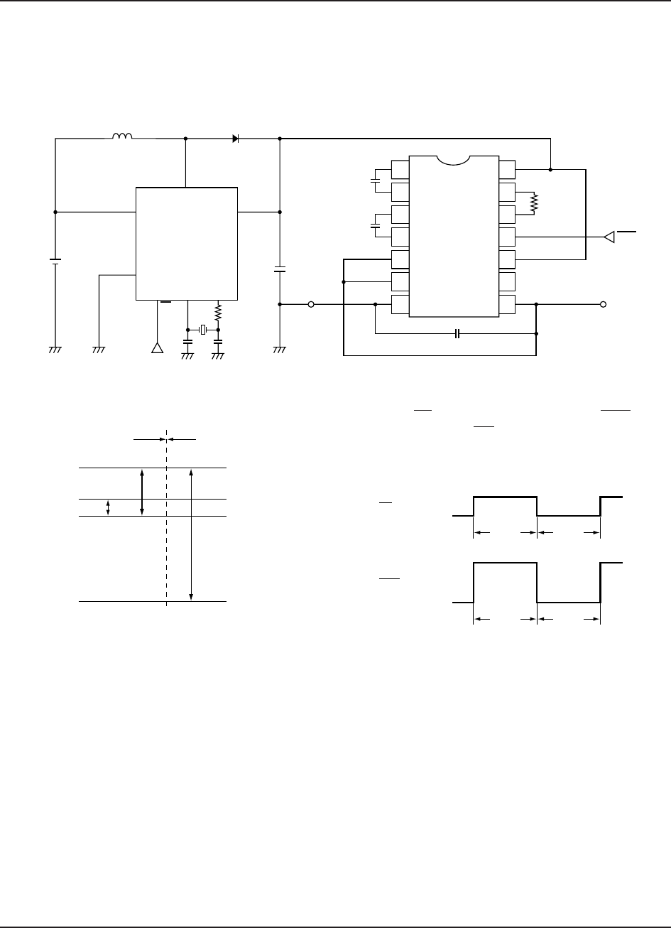
Voltage booster
Combining an S1F76330M1B0 switching regulator
with an S1F76610C/M DC/DC converter and voltage
regulator creates the voltage booster circuit shown in
the following figure.
Potential levels are shown in the following figure.
Although the circuit appears to have two ON/OFF con-
trol points, PS on the S1F76330M1B0 and P
OFF on the
S1F76610C/M, PS only shuts down the
S1F76330M1B0. The input voltage still reaches the
S1F76610C/M through L and D.
C
C1
10
µF
C3
10 µF
C2
10 µF
+
+
V
O
V
SW
L
D
V
I1
V
I
= –5 V
V
O
= –15 V
R
OSC
1 MΩ
P
OFF
GND
PS
C
G
C
D
R
D
S1F76330M
S1F76610C/M
1
2
3
4
5
6
7
14
13
12
11
10
9
8
S1F76610C/M
V
DD
(5 V)
V
DD
(0 V)
V
O
(–10 V)
V
O
(5 V)
V
I
(1.5 V)
GND
(0 V)
S1F76330M1B0
Boost
ON
V
I = 1.5 V
GND
= 0 V
PS
Boost
OFF
Boost
ON
V
I = 5V
GND
= 0 V
P
OFF
Boost
OFF