


S1F76300 Series
4–28 EPSON S1F70000 Series
Technical Manual
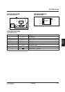
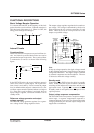
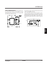
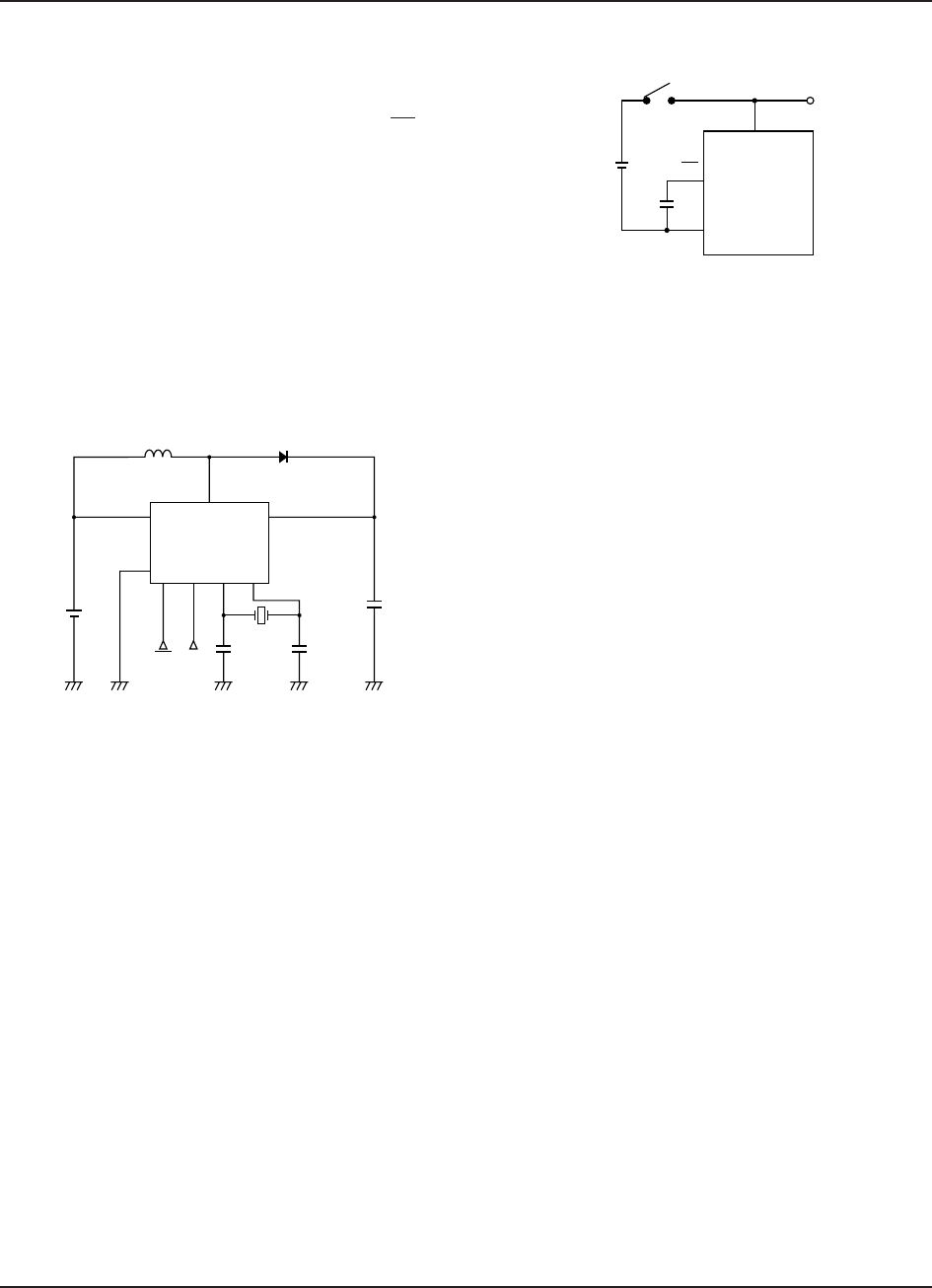
Powering up
Ensure that V
O is at least the minimum operating volt-
age (0.9V) before switching on the booster circuit. One
way to do this is to connect a capacitor between PS and
GND so that the chip connects V
O to VI when the power
is applied for the first time.
Inductor
Use an inductor with low direct-current resistance and
low losses.
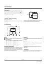
Leadless
Pre-wound, leadless inductors using surface-mount
technology are the most suitable for portable equipment
and other space-critical applications.
Drum coll
Avoid drum coils because their magnetic field can in-
duce noise.
Toroidal coil
Use a toroidal coil to virtually eliminate magnetic field
leakage, reduce losses and improve performance.
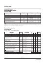
tors such as the switching frequency, type of coil, and
the size and type of other external components.
S1F76330 series
TYPICAL APPLICATIONS
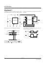
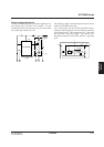
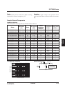
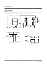
Example Circuits
The output current, IO, and power conversion efficiency
Peff, of a particular device in the series depends on fac-
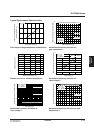
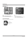
Notes
■ 100µH ≤ L ≤ 1mH, C ≤ 10µF, D: Schottky diode
■ S1F76330M1B0
• Peff = 70% when L = 220µH (leadless inductor),
V
I1 = 1.5V, fCLK = 32kHz, IO = 8mA
• Peff = 75% when L = 220µH (drum coil),
V
I1 = 1.5V, fCLK = 32kHz, IO = 9mA
• Peff = 80% when L = 300µH (toroidal coil),
V
I1 = 1.5V, fCLK = 32kHz, IO = 10mA
External Components
The performance characteristics of switching regulators
depend greatly on the choice of external components.
Observing the following guidelines will ensure high
performance and maximum efficiency.
V
I2
C
Battery
PS
S1F76330M
C1
V
O
C
G
C
D
C
rystal
V
SW
LD
V
I
GND
S1F76330M
PS CL
O